If your domain includes non-conformal boundaries between adjacent sections, you will need to "connect" them when you specify flow and/or thermal boundary conditions.
Important: As noted in Solution Technique for Non-Conformal Boundaries, it is recommended that the boundary with a coarser mesh should be specified as the "source" boundary, and the boundary with a finer mesh should be specified as the "target" boundary. If both boundaries have comparable mesh resolution, you can choose either one to be the source or target boundary.
To connect non-conformal boundaries, follow these steps (after selecting the boundary that will be the source boundary):
Select the Source of connected condition menu item in the list of boundary condition choices.
 Source of connected condition
In the resulting panel, select the corresponding target boundary.
Specify the numerical parameters related to the non-conformal boundary condition.
Specify the element dilatation, if necessary.
 Modify element dilatation
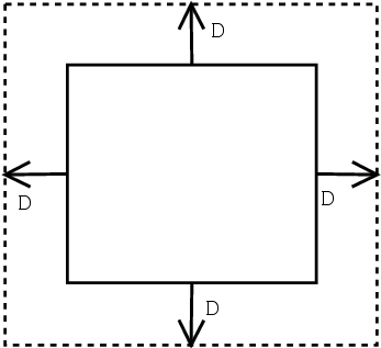
This option allows for expansion of each face of the source boundary in order to detect the corresponding face on the target boundary (see Figure 8.4: Element Dilatation). The default value is set according to the dimensions of the mesh, and you will generally not need to modify it. The element dilatation must be entered in the unit of length used for the mesh.
Specify the amplitude of the volume generation.
 Modify amplitude of volume generation
This value specifies the amount by which a source face can be expanded in order to detect the corresponding target face. The face is extended to a 3D volume in the local normal direction, by a constant amount that is precisely equal to the specified amplitude. This value must be entered in the unit of length used for the mesh.
Specify the stabilization factor, if necessary.
 Modify stabilization factor
This parameter controls the amount of fluid that is allowed to escape through faces that are connected to only one of the connected boundaries (that is, just to the source boundary or just to the target boundary). Ideally, no fluid should pass through these faces, but setting this value to zero will destabilize the solution. It is therefore set to a very small nonzero value, to avoid fluid loss without causing numerical instabilities. Change the value of this parameter from the default value only on the advice of your support engineer.
You can visualize the contact field in CFD-Post using Contact_V for the velocities, Contact_P for the stream function, and Contact_T for the temperature. Along the connected boundaries, a value of 1.0 means that the node is in contact (or is part of a conformity constraint), while a value of 0.0 means that the node is not in contact. If you observe that a node is not in contact when it should be in contact, you have to adapt the numerical parameters in the Options for connected boundaries menu: you should progressively increase (in several trials) the element dilatation and/or the amplitude of volume generation.


