The FloEFD solver wizard creates a parametric system containing FloEFD as the solver.
Note: Keep FloEFD open and the External optimizer mode activated during computation with optiSLang.
Creating a Task XML File
The task.xml file must be exported from FloEFD by creating an external optimization task.
Start FloEFD and open your model (*.sldasm).
Select .
Right-click your model in the tree and select .
Switch the study type to External Optimization Tool.
Switch to the Input parameter tab.
Select the required simulation, geometry, and construction table parameters and set their ranges.
Switch to the Output parameter tab.
Select the required targets and results.
Switch to the Scenario tab.
Select .
Save the task.xml file.
Using the optiSLang Solver Wizard
Once you have created the task.xml file, use it in the optiSLang Solver wizard.
Drag the Solver wizard onto the Scenery pane or an existing system.
Select FloEFD as the solver. Select the NGP_ParametricStudyStarter.exe executable file.
Browse for the FloEFD task.xml file.
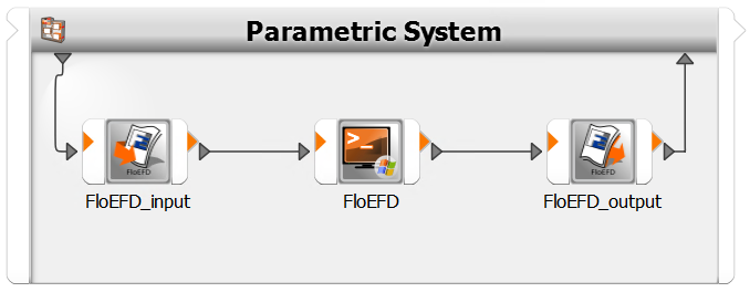
After selecting the task.xml file, the wizard automatically creates a parametric system containing the following solver chain:
FloEFD_input node to write inputs
Batch node to call FloEFD
FloEFD_output node to read results
Troubleshooting
What can I do if the wizard fails?
If a problem occurs during the wizard process, a log file (FloEFD_cw.log) with more detailed information is created in the same directory as your selected task.xml file. If you cannot fix the issue with the log file, contact Ansys Support (support@ansys.com).
How can I parallelize the FloEFD process?
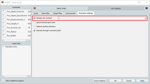
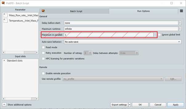
FloEFD is able to compute a set of designs in parallel with a single process on multiple machines. Set up this option in FloEFD on the Run Options tab, then set the number of designs per process in the Batch Script tab.
For these settings:
Do not change the Maximum in parallel setting because FloEFD cannot handle parallel processes
FloEFD limits the number of designs per process to 2