This tutorial allows you to create a conditional execution switch between two models.
This tutorial demonstrates how to do the following:
Create two simple modules using the calculator node
Create a conditional execution to switch between the two models depending on a given condition
Perform a sensitivity analysis with the conditional solver chain.
To set up and run the tutorial, perform the following steps:
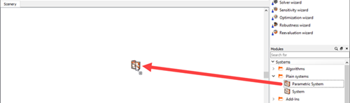
Under Modules, expand and .
Drag a Parametric System node onto the Scenery pane.
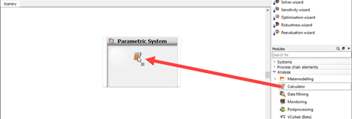
Under Modules, expand .
Drag a Calculator node onto the Parametric System.
Select the Receive design from parent system and Send design back to parent system check boxes.
Click .
Repeat steps 4-6 to add a second calculator to the Parametric System.
Right-click the Calculator node and select from the context menu.
Type
Model1and press Enter.Right-click the Calculator (1) node and select from the context menu.
Type
Model2and press Enter.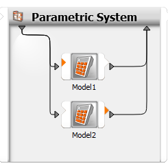
Double-click the Parametric System.
On the Parameter tab, right-click the empty pane and select from the context menu.
In the number box, enter
3.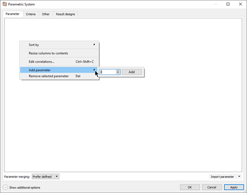
Click .
In row 1, double-click the Name cell and enter
x1.Double-click the Parameter type cell and select from the list.
Repeat steps 5 and 6 for the next two parameters, naming them
x2andx3.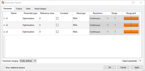
Click .
From the menu bar, select > .
Switch to the Advanced tab.
From the Conditional execution tab visibility list, select .
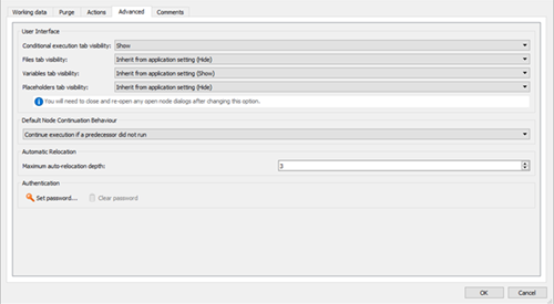
Click .
Double-click the Model1 node.
Click .
Double-click the ID cell for the new variable, type
y, and press Enter.Double-click the Expression cell, type
x2+0.5*x3, and press Enter.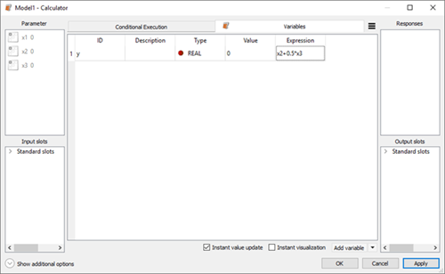
Click .
Double-click the ID cell for the new variable, type
model, and press Enter.Double-click the Expression cell, type
1, and press Enter.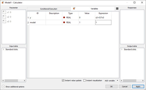
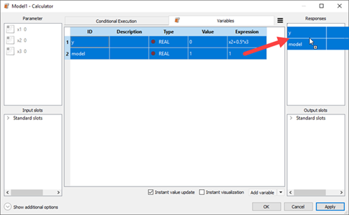
Select both variables and drag them to the Responses pane.
Switch to the Conditional Execution tab.
Click .
Type
x1>x2and press Enter.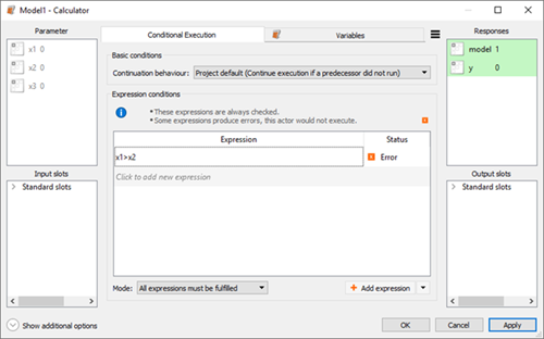
To close the dialog box, click .
Double-click the Model2 node.
Click .
Double-click the ID cell for the new variable, type
y, and press Enter.Double-click the Expression cell, type
x1+0.5*x3, and press Enter.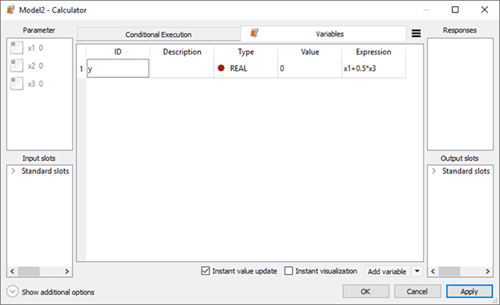
Click .
Double-click the ID cell for the new variable, type
model, and press Enter.Double-click the Expression cell, type
2, and press Enter.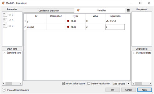
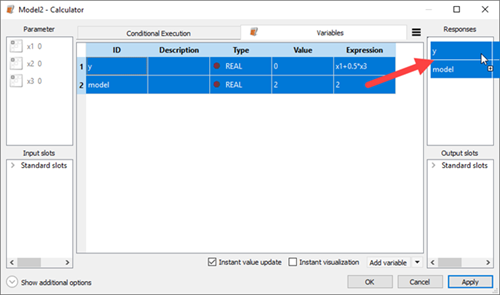
Select both variables and drag them to the Responses pane.
In the warning dialog box, ensure that Add response with this name is selected and click .
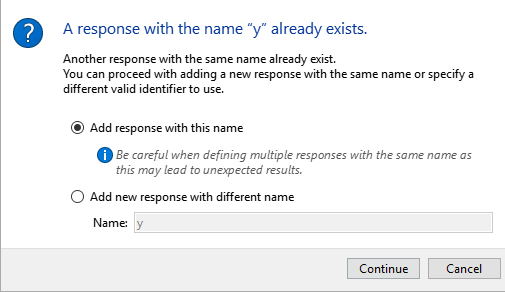
Both conditional nodes write their results to the same response objects.
Switch to the Conditional Execution tab.
Click .
Type
x1<=x2and press Enter.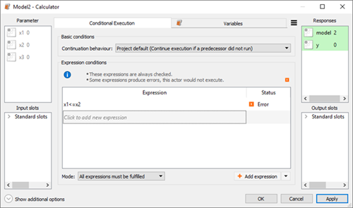
To close the dialog box, click .
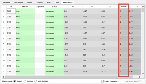
Now the solver chain consists of two parallel models which will be executed depending on the values of x1 and x2. If a registered response is written by only one node for one design, the design succeeded, but if a response is written by two nodes for the same design, the design will fail.
In this example, the conditions have been chosen so that only one can be true at one time.
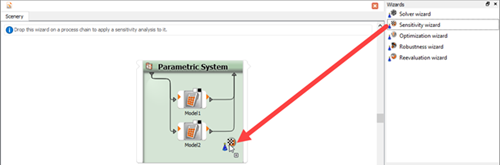
From the Wizards pane, drag the Sensitivity wizard to the Parametric System and let it drop.
Run through the wizard, accepting all of the default values.
To close the dialog box, click .
To save the project, click
 .
.Browse to the location to save the project and type a project name in the File name field.
Click .
To run the project, click
 .
.Hovering the mouse over each conditional node shows how many designs have been executed. The skipped designs occur due to the conditions being false.
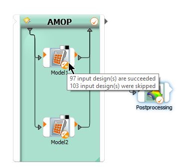
In this example, the model response displays which model is used to calculate y for each design.