This tutorial allows you to complete a calibration of a single degree-of-freedom system excited with initial kinetic energy.
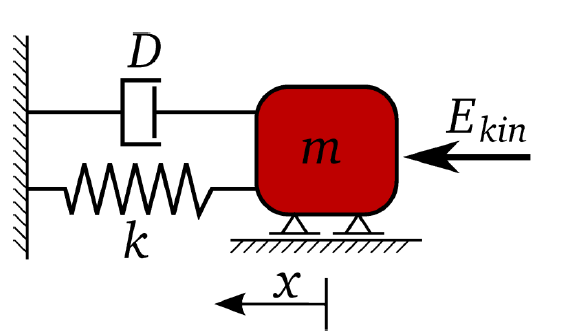

The equation of motion of free vibration is:

The undamped and damped eigen-frequency is

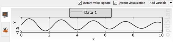
The time-dependent displacement function is:

The goal is the identification of the input parameters m, k, D, and Ekin to optimally fit a reference displacement function.

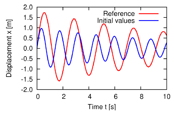
The objective function is the sum of squared errors between the reference and the calculated displacement function values.

This tutorial demonstrates how to do the following:
Generate a solver chain using Twin Builder
The representative for all model types offered by Ansys Electronics Desktop
Define the input parameters
Define the output and reference signals
Note: This tutorial walks you through a single problem. For more detailed information and best practices, see Ansys EDT in the optiSLang User's Guide.
Before you start the tutorial, complete the following tasks:
Download the oscillator_signals_twinbuilder zip file from here , and extract it to your working directory.
Copy the oscillator.aedt file from the zip file extracted in step 1 to a new workspace folder (recommended).
Launch Twin Builder.
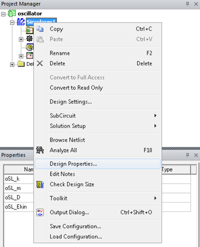
In the Project Manager, right-click Simplorer1 and select from the context menu.
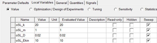
Switch to the Local Variables tab.
Verify that the following variables are displayed:
To close the dialog box, click .
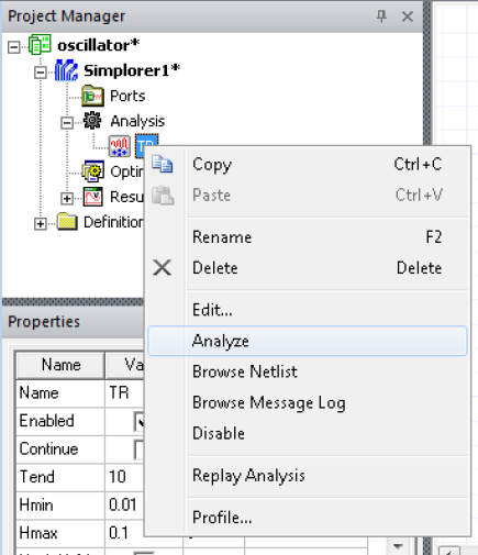
In the project tree, expand Analysis.
To solve the model, right-click the TR node and select from the context menu.
In the project tree, expand Results.
Verify that result reports are defined.
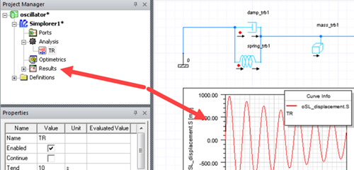
Response collection in optiSLang is based on exported reports.
Close the project and exit Twin Builder.
Best Practice Recommendations for Directory Structures
Flexible file and folder references:
Files and folders can be referenced in absolute and relative manner
Referenced files may be located relatively nearby or far away
optiSLang has many ways to handle referenced paths very flexibly
In collaborative environments, far-reaching references are often a necessity (for example, network server drives)
This tutorial however,
Comes as a small package with all necessary files
Can be considered as self-sufficient encapsulated project
Can be revisited later
You will soon develop your own suitable best practice
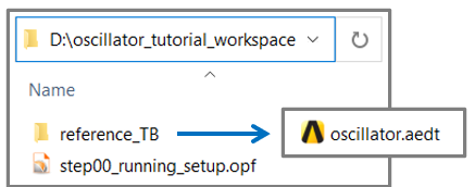
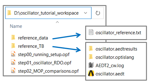
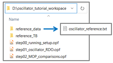
The following image depicts a folder structure you can use as a good starting point.
To set up and run the tutorial, perform the following steps:
Start optiSLang.
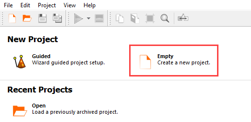
Create a new empty project.
This tutorial provides instructions for manually connecting input and output slots. To display the slots in the node flyouts, from the menu bar select > > .
Important: Ensure that the oscillator.aedt project is closed before starting this procedure.
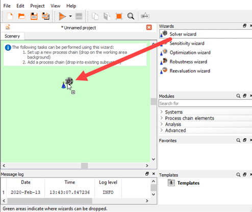
From the Wizards pane, drag the Solver wizard to the Scenery pane and let it drop.
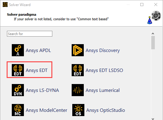
From the solver list, click .
In the Select project file dialog, browse to your working directory and select oscillator.aedt.
Click .
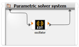
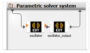
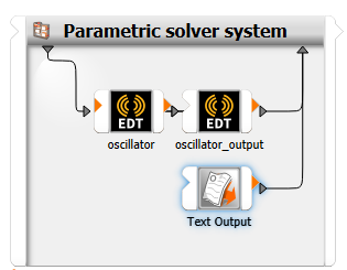
The Solver wizard creates a parametric system containing a single Ansys EDT integration node
From here, you can now create a one node setup or a two node system.
The two node system is a best practice procedure offering several advantages that pay off during later work with your process integration setup. This setup is recommended.
Double-click the oscillator node to edit it, or right-click the node and select from the context menu.
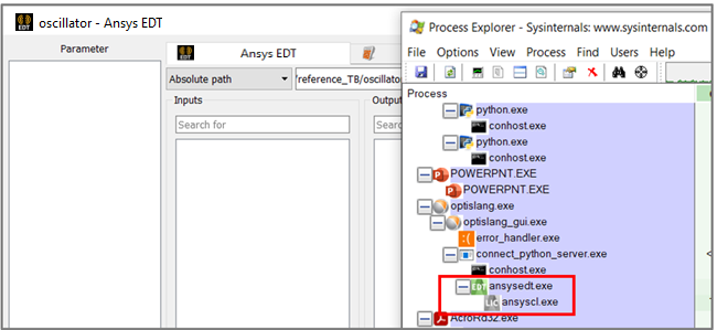
The Ansys EDT integration node wants to display properties of the referenced project. This triggers a sequence of actions.
An instance of Electronics Desktop is opened in the background,
Ansys EDT opens the reference project,
Parameters and reports are extracted as part of a first-time inquiry,
The edit dialog stays empty and non-responsive during this process,
Once the reference project inquiry has successfully yielded results, parameter and response listings will appear and the dialog becomes responsive again.
The same project inquiry sequence is executed again after modifications are made to the reference project. Once any referencing integration node detects a timestamp or other inconsistency between the Ansys EDT file and the stored inquiry results, the inquiry procedure is triggered.
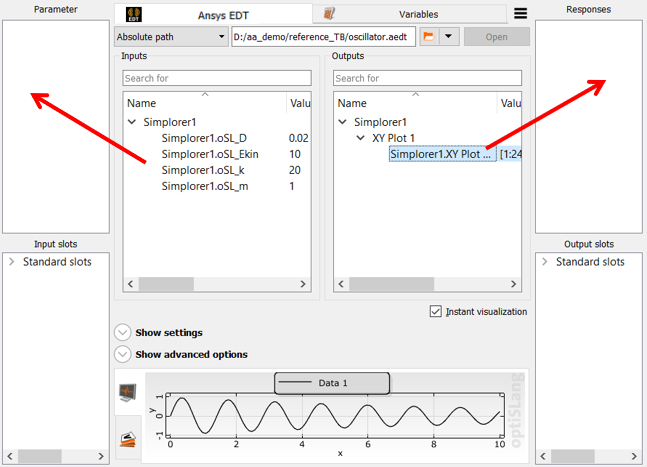
In the Inputs pane, select the displayed parameters and drag them into the Parameter pane to register them.
In the Outputs pane, expand Simplorer1 and XY Plot 1.
Drag Simplorer1.XY Plot to the Responses pane to register it.
To save the changes and close the dialog box, click .
To save the project, click
 .
.Browse to the location to save the project and type a project name in the File name field.
Click .
To run the project, click
 .
.
This is the end of the single node setup process. You can now use this single node project with other oscillator tutorials.
This setup process creates a two node system following best practice recommendations. This covers:
Two-node setup with a separate output collector node.
Shared parametrization mode.
Achieving updated listings after altering settings.
Tree-view and tabular displays.
How to best rename responses registered from the primary detection listing.
Best directory structure.
These steps allow you to gain reset-rerun capability for output collection. Resetting only the output collector node leaves the work directories and the finalized state of the preceding solver node intact. This is possible for single-iteration systems, for example, sensitivity or robustness samplings.
Right-click the oscillator node and select from the context menu.
Right-click the Parametric solver system and select from the context menu.
Drag the oscillator (1) node onto the connection line.
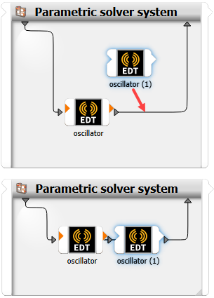
Right-click the oscillator (1) node and select from the context menu.
Rename the node as desired. In this example, the node is renamed to oscillator_output.
Double-click the oscillator node or right-click the node and select from the context menu.
Click .
Select the and check boxes and clear the check box.
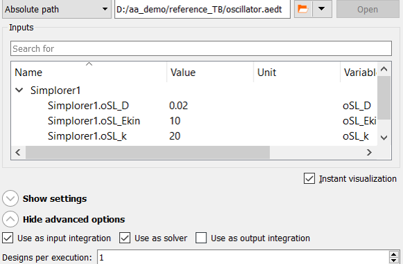
Setting the file path relative to the project (the OPF file) will also work and make the workspace easily portable, but setting the path relative to the working directory does not work. The first node has to start by cloning the baseline project into its working directory.
To save the changes and close the dialog box, click .
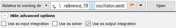
Double-click the oscillator_output node or right-click the node and select from the context menu.
From the path list, select .
It is a long established optiSLang standard and perspective that input integrations are cloning master files given in a constant location, whereas pure output collection is to happen in ever changing working directories.
Click .
Select the check box and clear the and check boxes.
To save the changes and close the dialog box, click .
Double-click the oscillator node or right-click the node and select from the context menu.
Switch to the Settings tab.
On the Parameters tab, select the following check boxes:
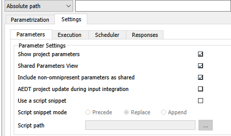
By default, parameter names are prefixed based on the models within the Ansys EDT project. The oscillator project contains only one model and the prefix is unnecessary.
Shared parametrization is convenient if multiple models within a project are to be kept in sync and/or for creating short parameter names.
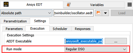
Switch to the Execution tab.
Verify that the Ansys EDT executable is ansysedt.exe.
If it is something different or there is no text in the field, click the ellipses button to the right of the field. Browse to C:\Program Files\AnsysEM\AnsysEM 24.2\Win64 and select the executable file.
From the Run mode list, select .
Ensure that the No GUI check box is selected.
Optionally, to force the analysis to wait for a license when running. select the Wait for AEDT license check box.
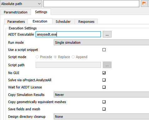
To save the changes, click .
To force a reference data reload, click .
If the button is not active, click
 , then close the file
browsing dialog box without selecting a file.
, then close the file
browsing dialog box without selecting a file. The parameters are reloaded and the parameter names are shortened.
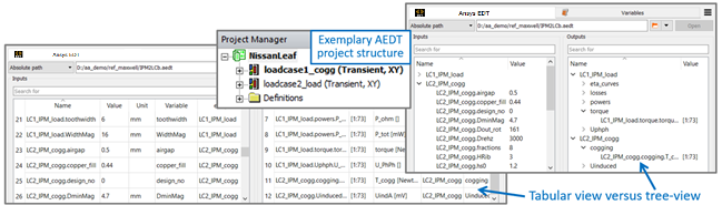
You can display inputs and outputs for an integration node in a tabular view or tree view. Both views contain the same information. The tree view works well for mirroring the structure of Ansys EDT projects comprising multiple models.
In the menu bar, select > .
Under Customization, select or clear the Customized integrations use treeview check box.
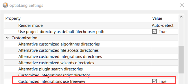
Click .
Save the project and restart optiSLang.
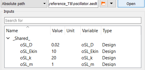
In the oscillator node Inputs pane, select the displayed parameters and drag them into the Parameter pane to register them.
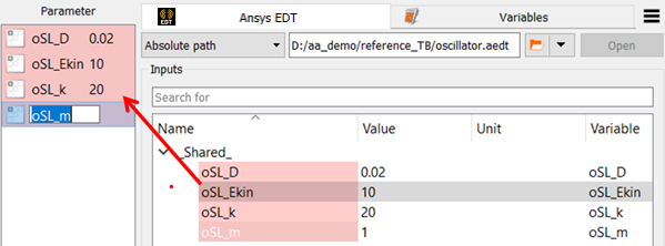
In the Parameter pane, click the parameter names and change them to
D,Ekin,k, andm.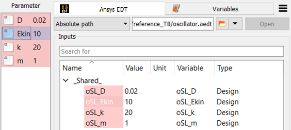
Highlighting selected parameters can show the connection to the new names.
To save the changes and close the dialog box, click .
Double-click the oscillator_output node or right-click the node and select from the context menu.
In the Outputs pane, expand Simplorer1 and XY Plot 1.
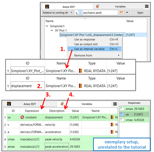
Right-click Simplorer1.XY Plot1 and select from the context menu.

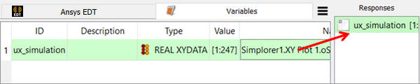
Switch to the Variables tab.
Select the displayed variable and drag it into the Responses pane to register it as the response signal.
Recommendations for Response Renaming
Avoid renaming in the Responses pane as depicted below. The obvious connection between renamed responses and their origin can be lost.
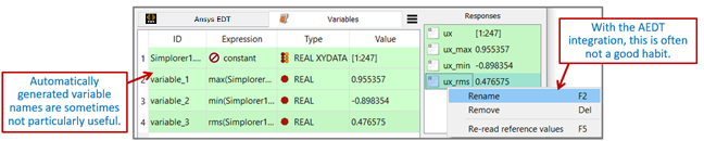
If the formula expressions for derived quantities are lengthy or otherwise complex, the connection between renamed responses and their origins in the integration node’s response listing and the calculator listing may not be obvious anymore.
Highlighting selected quantities may be the sole way to regain knowledge about the actual connections.
A setup like above is not in the best shape for revealing its logic to somebody viewing it later, it is not at all self-documenting.
From the outputs listing, register relevant objects as an internal variable. The advantage when renaming only in the Variables tab in the definition listing, the Name column provides the connection of the new given name to the original automatically detected name, so it is always documented.
Register chosen listed objects as an internal variable. They are displayed in the Variables tab.
Use the ID column of the table for renaming.
Use the calculator for deriving further quantities of interest by adding variables from the context menu.
Use help variables (remaining unregistered) and the Description column for further enhancing clarity and documentation.
Double-click the Parametric solver system.
Set the Range numbers as shown in the following image.
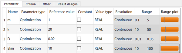
Click .
In the Modules pane, expand Process chain elements and Output nodes.
Drag the Text Output node into the solver chain.
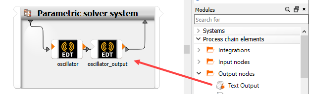
In this example, the Text Output node is used, but you can also use the ETK (extraction toolkit) node. The ETK node has more diverse features and fulfill the output collection task equivalently.
Clear the Receive design from parent system check box.
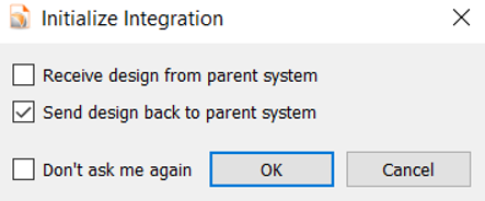
To save the changes and close the dialog box, click .
The Text Output node is added to the system.
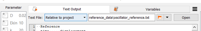
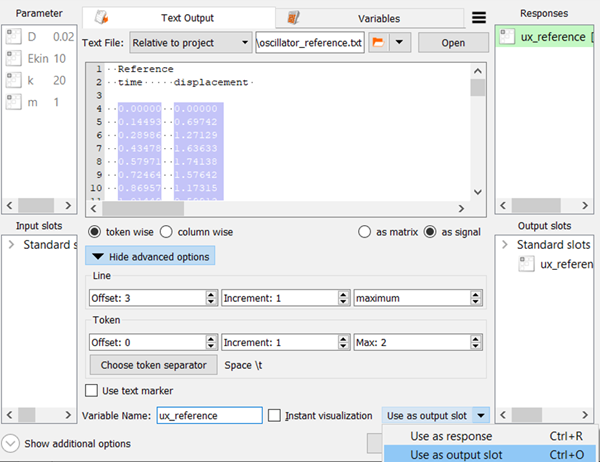
Double-click the Text Output node or right-click the node and select from the context menu.
Click
.Browse to the twin_builder folder and select oscillator_reference.txt.
Click .
Select as the search mode.
When referencing a far-away location like a server drive, then the absolute mode is recommendable.
When working in a self-sufficient project workspace with all ingredients assembled, as shown in the following image, then the relative mode is recommendable and provides seamless portability.
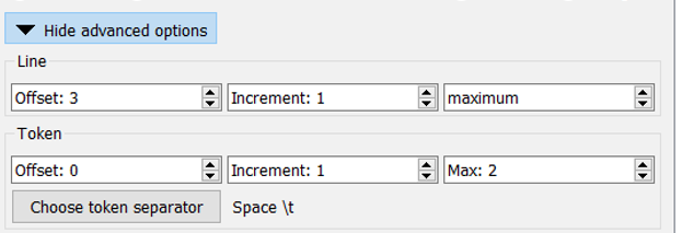
Expand Show advanced options.
Set the Line and Token settings as shown.
In the Variable Name field, type
ux_reference.From the multi-action button, select .
The signal is displayed in the Responses pane.
From the multi-action button, select .
The signal is displayed in the Output slots pane.
Click .
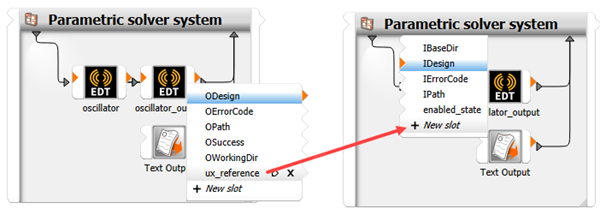
Hover over the right side of the Text Output node to open the output slots flyout.
Click ux_reference and drag it onto New slot on the input slots flyout (left side) of the oscillator_output node.
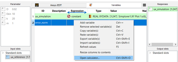
Double-click the oscillator_output node or right-click the node and select from the context menu.
Switch to the Variables tab.
Click .
Double-click the ID cell for the new variable, type
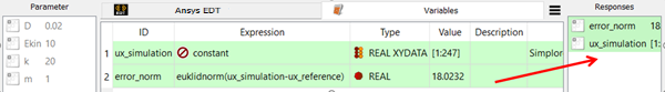
error_norm, and press Enter.Right-click the Expression cell of row 2 (error_norm) and select from the context menu.
Note that the column order in the variables tab is flexible. Columns can be moved by dragging the header fields. The column for formula expressions can be moved to the left in order to have most relevant fields like variable names, expressions, and result values displayed closer together in a more compact area.
In the calculator, switch to the Linear Algebra tab.
Click .
In the brackets, type
ux_simulation-ux_reference.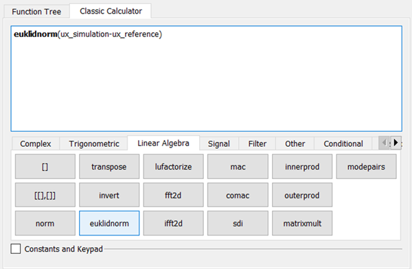
In this step, you are specifying the simulated signal minus the reference signal as the input for the euklidnorm function.
Click .
Select the Instant visualization check box and compare the simulated signal with the reference signal on the slot. Also double check the units, you may correct the signal with scaling.
Drag the error_norm row into the Responses pane to register it as a response.
Click .
To save the project, click
.Browse to the location to save the project and type a project name in the File name field.
Click .
To run the project, click
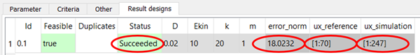
.To review the result, double-click the Parametric solver system and switch to the Result designs tab.
If you encounter problems with the project, see the Troubleshooting section of Ansys EDT in the optiSLang User's Guide.
You can also try different run modes, for example simulation of multiple designs with DSO.