This tutorial explains how to use the Apply Measurement option in the ACT plugin for Ansys Mechanical to apply displacement of nodes of a mesh by measurement on another geometry. Once you load the ACT plugin, the workflow is to edit the Mechanical model in an Ansys Workbench project and generate a new "geometry":
Select the set of moved nodes.
Select the set of fixed nodes.
Specify the name of the new "geometry'" to create.
Select the part or parts to use.
Generate the new "geometry" by setting files to call the oSP3D mapping algorithm that applies displacement on the input mesh for the solver.
The following topics explain how to use the supplied Workbench project file simple_cube.wbpz to try out the Apply Measurement option:
To set up the Workbench project:
In Workbench, open the file simple_cube.wbpz in
oSP3D_examples\ansys\simple_cube.Rename the project file as simple_cube_tutorial4 and save it in the same folder.
If you see a message indicating that the oSP3D extension will be upgraded permanently when you save the project, click .
To edit the Mechanical model and generate the new "geometry":
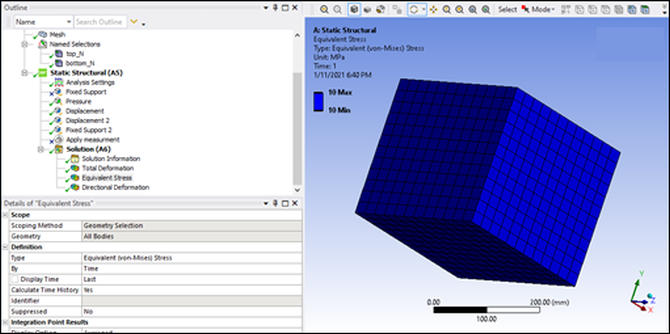
In the Workbench Project Schematic, right-click the Model cell and select Edit to open the model in Mechanical.
In the Outline view, select Mesh.
In the Mechanical ribbon, select >
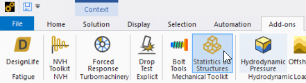
Select > .
In the Outline view under Static Structural, an Apply measurement node is added.
Select the Apply measurement node.
In the Details view, the properties required are:
A set of nodes that are moved by the target geometry (geometry selection or named selection)
A set of nodes that are fixed on the initial mesh (geometry selection or named selection)
Mesh part selection (geometry selection or named selection)
Scan data file (STL, DAT, or CDB) to serve as the target for the moved nodes
Maximum search distance value for use in the oSP3D algorithm that detects the geometry deviations
This image shows how to complete the required properties for this tutorial.
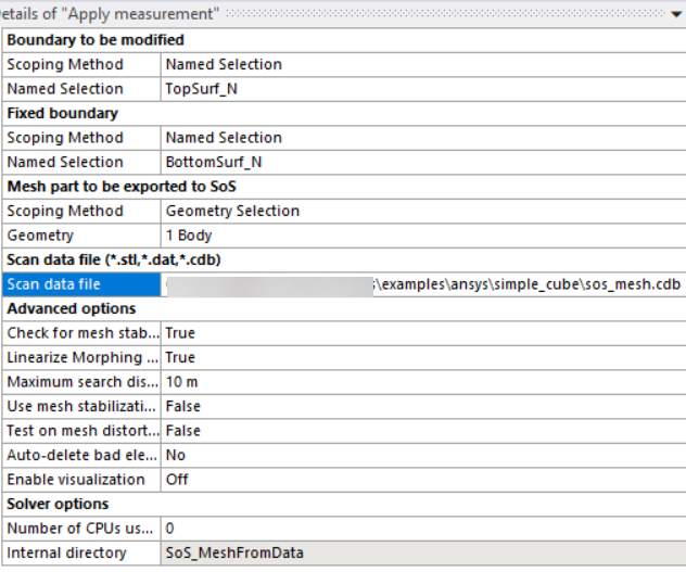
The set of moved nodes is a named selection:
TopSurf_N.The set of fixed nodes is a named selection:
BottomSurf_N.The mesh part is selected by clicking the part.
The scan data file is sos_mesh.cdb in
oSP3D_examples/ansys/simple_cube.The maximum search distance value is
10.
To define the displacement, in the project tree, right-click Apply measurement and select Generate.
The following results are generated:
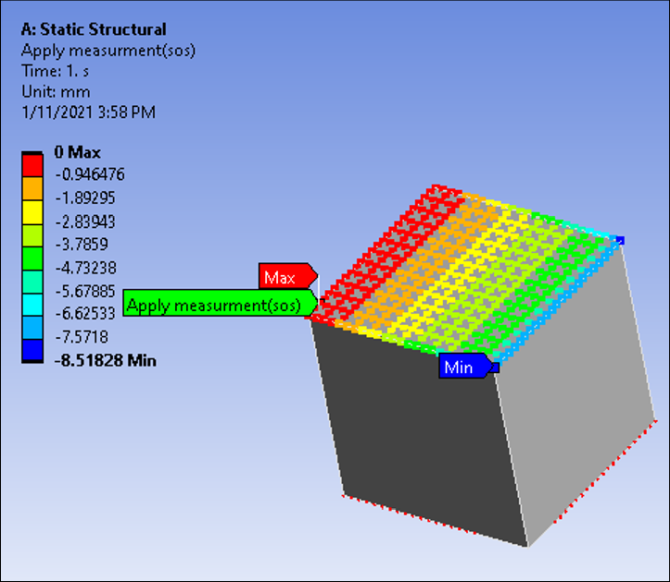
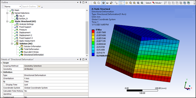
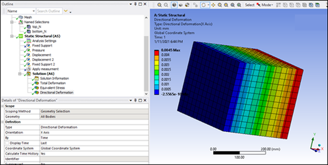
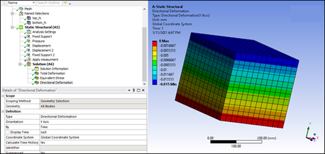
The STL file shows that the top face is not parallel to the bottom face. The edge is displaced 5 mm.
The boundary condition is a pressure on the top surface. This means that the STL geometry creates a non-null deformation along the axes:
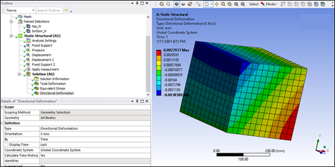
You can verify this by not using the target geometry in the STL file. The result is that the deformation along the X axis is constant in the Y direction.
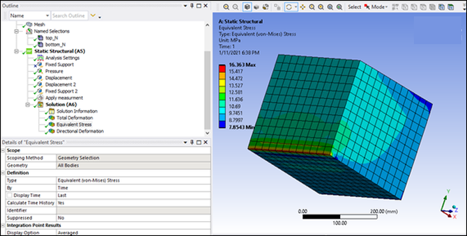
The equivalent stress is constant: