

The Restart Analysis add-on allows you to reuse the Base Analysis in separated analysis systems to insert different loads and boundary conditions and compare their effects on the model.
This tutorial demonstrates the capabilities of the Restart Analysis add-on. You will use the Restart Analysis capabilities on a multiple load step static structural analysis of a shaft under multiple types of loads and boundary conditions.
| Analysis Type | Static |
| Features Demonstrated | Restart Analysis Add-on, Restart Analysis system creation, Restart Analysis object addition, loads applied by Surface Effect modification in a Restart Analysis system |
| Licenses Required | Ansys Mechanical Enterprise PrepPost and Ansys Pro/Premium/Enterprise |
| Help Resources | Restart Analysis Add-on |
| Tutorial Files | RestartAnalysisAddOn.zip |
This tutorial guides you through the following topics:
- 27.1. Access Data Files
- 27.2. Configure the Restart Analysis Add-on
- 27.3. Define the Base Structural Analysis
- 27.4. Restart the Analysis with a Force Load
- 27.5. Restart the Analysis with a Pressure Load
- 27.6. Review and Validate the Results
- 27.7. Appendix: Modify Loads Applied by Surface Effect in Restart Analysis
Data files for this tutorial can be found here on the Ansys customer site.
The zip folder contains the following files:
Shaft_Bearings_Start.wbpz - this is the input model that you will set up during the steps defined below. Copy this file to a working folder and complete the worked example.
Shaft_Bearings_Completed.wbpz - this is an example of the completed model once all the steps have been followed.
Shaft_Bearings_Appendix_Completed.wbpz - this is an example of the completed model once all the steps in the Appendix have been followed.
Start Workbench and select > .
Browse to the working folder and select Shaft_Bearings_Start.wbpz.
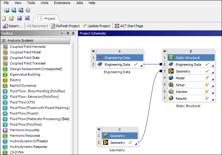
This Workbench project contains the Static Structural system.
Double-click the Model cell to open Mechanical.
To enable the Restart Analysis capabilities, click the icon in the tab.
The icon is highlighted in blue, indicating that the add-on is loaded.
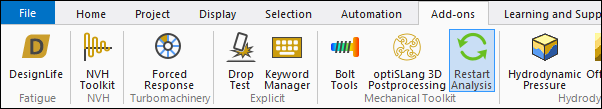
Once the add-on is loaded, the Restart Analysis tab is visible with all the Restart Analysis capabilities.
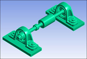
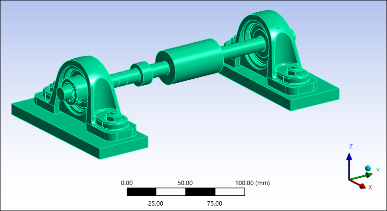
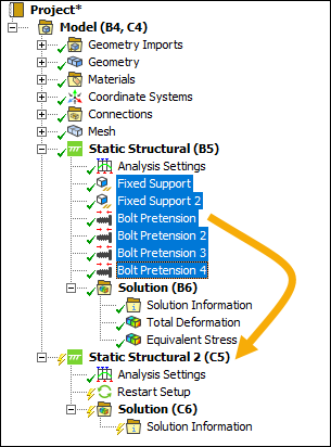
The model consists of multiple solid parts. To view the model parts and bodies, expand the object in the tree Outline.
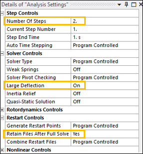
In the Details pane for the Analysis Settings, expand the Step, Solver, and Restart Controls. Make sure the model contains two load steps, Large Deflection is set to On, and Retain Files After Full Solve detail is set to Yes.
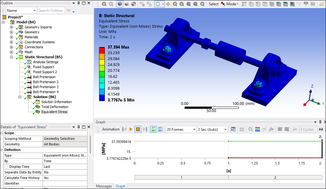
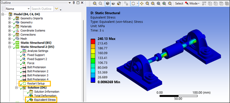
Insert Total Deformation and Equivalent Stress results to the Solution object.
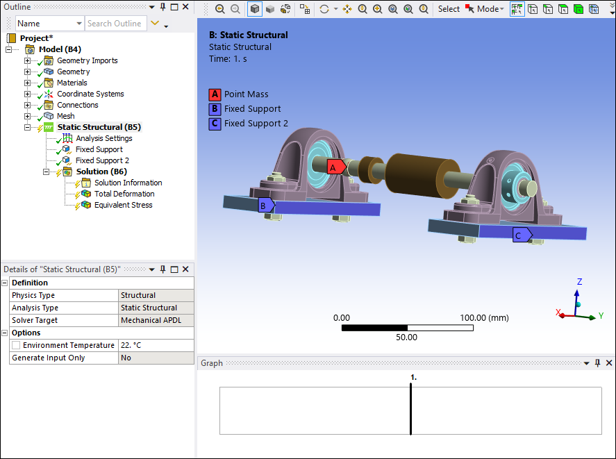
Define the supports
Insert a Fixed Support and scope it to the two long side faces of one of the Ground bodies.
Right-click the newly created Fixed Support and click Duplicate. Edit the Geometry scoping by clicking the Geometry: 2 Faces field in the Details pane.
Select the two long side faces of the other Ground body and click Apply in the Geometry field.
Define the Bolt Pretensions
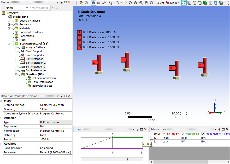
Insert four Bolt Pretension elements under Static Structural.
Expand the Geometry list in the Outline pane and hide all bodies except the ones named bolt\bolt by right-clicking each body and selecting Hide Body.
Scope each bolt’s shaft face into the Geometry property of each Bolt Pretension.
Insert a preload of
1000 Ninto load step 1 of each Bolt Pretension. Insert a bolt Lock into load step 2.
Right-click any body in the Geometry list in the Outline pane and select Show all Bodies. Right-click the Solution object in the tree Outline and select Solve. During the solving process, you can click Solution Information to view the solver's progress and errors as they are encountered.
The Base Structural Analysis is completed.
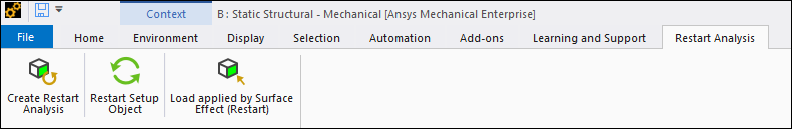
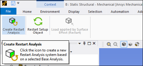
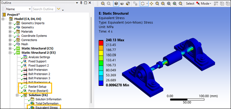
In the tree Outline, select the Base Analysis, Static Structural (B5). From the Restart Analysis tab, select Create Restart Analysis to create a new Restart Analysis system based on the selected Base Analysis.
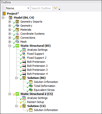
Verify that the Static Structural 2 (C5) object is inserted into Mechanical.
Alternatively, you can also create a new Static Structural Analysis and add the Restart Setup object to the analysis, then select the Base Analysis (B5). However, you need to ensure that the new analysis has a number of load steps greater than the Base Analysis and has the same analysis settings (for example, the Large Deflection property).
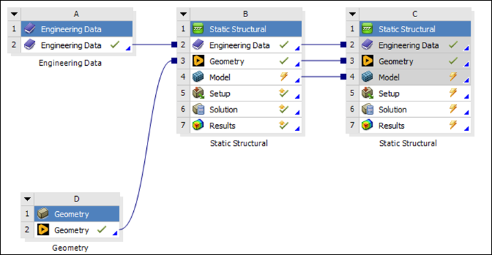
Return to the Project Schematic in Workbench. The new Static Structural system is incorporated into the schematic, connects to and shares the Engineering Data, Geometry and Model cells with the Base system.
In the Outline pane of Mechanical, select all boundary conditions from the Base system, Static Structural (B5), and drop them into the Restart Analysis system, Static Structural (C5).
Insert a Force load to the Restart Analysis system, then scope it to the external face of the Pulley2 body and the selection.
Set the Define By property to Components, then set the Applied By property to Direct. Add a
2000 Nforce to the X component of load step 3 and make sure that the X component of load step 2 is set to0 Nas shown below in the Tabular Data.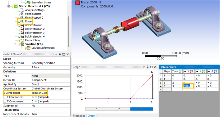
Insert Total Deformation and Equivalent Stress results to the Solution object, then solve the system.
Follow steps 1 to 4 of the Restart the Analysis with a Force Load section to create another Restart Analysis system.
Insert a Pressure load to the new system. Scope the Pressure load to the external face of Pulley2 and the selection.
Set the Define By property to Components, then set the Applied By property to Direct. Add a
0.2 MPapressure on the X component of load step 3 and make sure that the X component of load step 2 is set to0 MPaas shown below in the Tabular Data.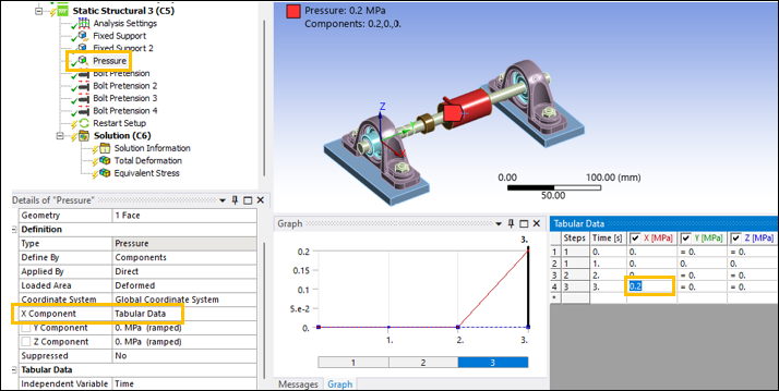
Insert Total Deformation and Equivalent Stress results to the Solution object, then solve the system.
You can validate the accuracy of the results by performing the same type of analysis in a stand-alone system from start to finish.
Return to the Project Schematic in Workbench and duplicate the Base Analysis system. Keep the upstream connections from the rest of the project when prompted. Rename the new system as
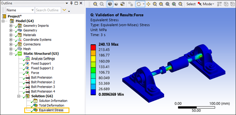
Validation of Results: Force, then click Model in the validation system to open Mechanical.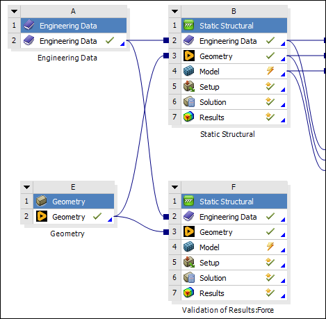
Expand the Step Controls in the Details pane for Analysis Settings. Make sure the model contains three load steps.
Insert a Force load, scope it to the external face of the Pulley2 body and Apply the selection.
Set the Define By property to Components. Add a
2000 Nforce on the X component of load step 3 and make sure that the X component of load step 2 is set to0 N.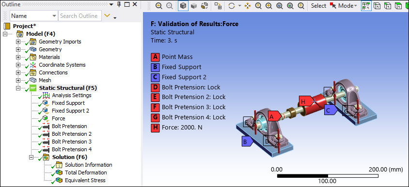
Insert Total Deformation and Equivalent Stress results for validation purposes, then solve the system.
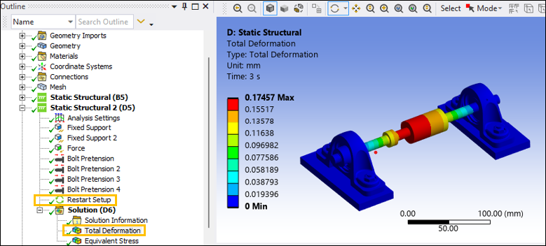
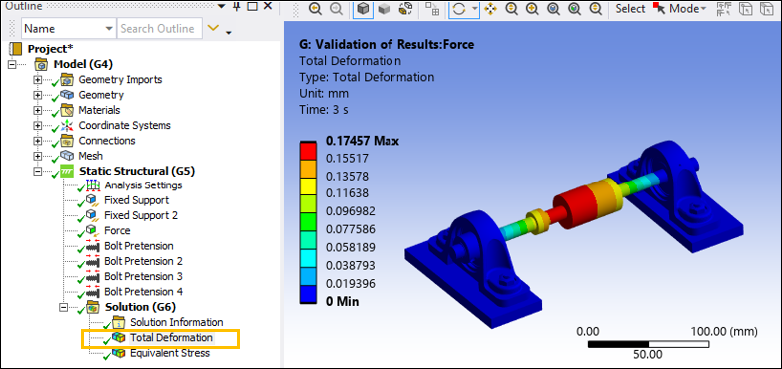
The Total Deformation and Equivalent Stress results for the Force analyses are depicted below:
Force Load in Restart Analysis and Stand-Alone Systems: Total Deformation Results
Force Load in Restart Analysis and Stand-Alone Systems: Equivalent Stress Results
In a Restart Analysis, Force, Pressure, Imported Pressure, or Hydrostatic Pressure loads are permitted only with the Applied By property set to Direct, unless a Nonlinear Adaptive Region is defined in the Base Analysis. To learn more about limitations for loads in a Restart Analysis, see Limitations for Loads and Boundary Conditions.
If the loads (Pressure or Force) transferred from the Base Analysis are applied by the Surface Effect option, they can be modified in the Restart Analysis by following these steps:
Define a Base Analysis by following the steps in the Define the Base Structural Analysis section.
In the Details pane for the Analysis Settings, expand the Step Controls and set the Number of Steps property to
3.Insert a Force load in the Base Analysis. Scope it to the external face of Pulley2 and Apply the selection. Set the Applied By property to Surface Effect. Set the Define By property to Components, then add a
1000 Nforce on the X component of load step 3.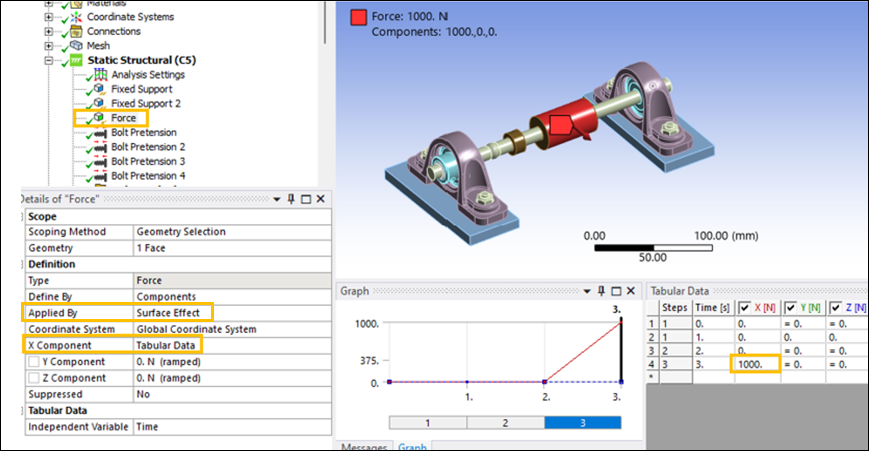
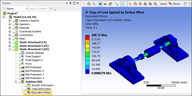
Right-click the Static Structural object and select Duplicate.
Click the newly created system, then select Restart Setup Object from the Restart Analysis tab to add the object to the analysis.
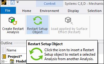
Select the Restart Setup object within the new system, then click Load Applied by Surface Effect (Restart) in the Restart Analysis tab.
Alternatively, right-click the Restart Setup object and select Insert > Load Applied by Surface Effect (Restart).
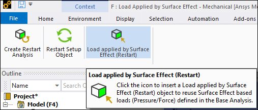
Configure the settings in the Details pane as follow:
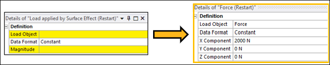
The modified Force load is now 2000 N in magnitude and will be applied in load step 4.
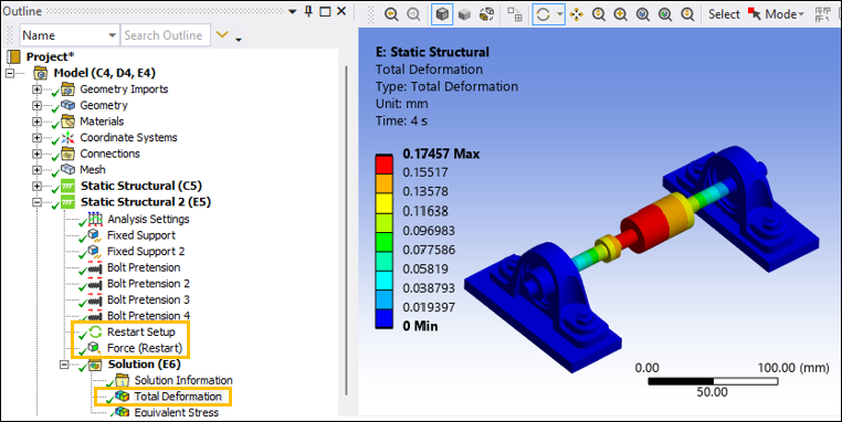
Solve the Restart Analysis system.
Validate the Results
Follow these steps to validate the results:
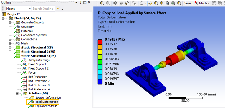
Duplicate the Base Analysis. In the Analysis Settings of the newly created analysis, insert
4into the Number of Steps property.Modify the Force load's Tabular Data to include a ramp up of Force of
2000 Nin load step 4.Solve the analysis and compare the Total Deformation and Equivalent Stress results with the Restart Analysis system.
Force Load in Restart Analysis and Stand-Alone Systems: Total Deformation Results
Force Load in Restart Analysis and Stand-Alone Systems: Equivalent Stress Results
Congratulations! You have completed the tutorial.