


This tutorial illustrates a fracture analysis of a 2D cracked specimen under a tensile load. The crack is modeled at the geometry level and the appropriate mesh controls are already defined. The fracture parameters are post-processed using a J-Integral approach that supports plastic material behavior.
| Analysis Type | Fracture |
| Features Demonstrated | Restoring archive, Engineering Data, material assignment, nodal Named Selections, coordinate systems, crack definition, fracture results |
| Licenses Required | Ansys Mechanical Enterprise/Enterprise Solver/Enterprise PrepPost |
| Help Resources | Fracture Analysis, Defining a Pre-Meshed Crack |
| Tutorial Files | 2D Cracked Specimen.wbpz |
This tutorial guides you through the following topics:
Open Ansys Workbench.
Select > .
Browse to open 2D Cracked Specimen.wbpz. This file is available here on the Ansys customer site.
Save the project in a desired directory - click and when prompted.
Review material properties in Engineering Data.
Right-click the Engineering Data cell and select Edit. The Engineering Data workspace opens.
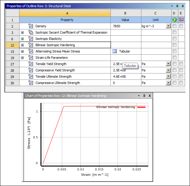
Select the Structural Steel material and, in the Properties window, select the Bilinear Isotropic Hardening law. Review the Chart of Properties.
Return to the project schematic by selecting the Project tab.
Prepare the analysis in Mechanical: Right-click the Model cell and select Edit. The Mechanical application opens and displays the model.
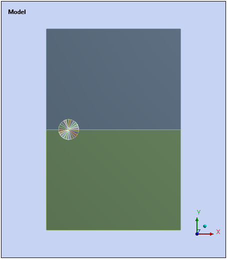
Note: Geometry and Mesh Controls have been predefined in the project. The Geometry consists of two parts that represent the two different sides of the crack.
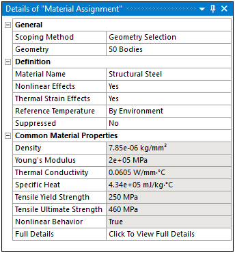
Specify Material Assignment for all bodies. To calculate the most accurate results, use the Material Assignment feature to assign each body, of each part, the same material identifier (ID).
Right-click the Materials folder and select > .
Select the entry field of the Geometry property.
Select all bodies of the model: Right-click in the Geometry window and select .
Click the Apply button in the entry field of the Geometry property.
Select the entry field of the Material Name property, open the flyout menu, and select Structural Steel as the material.
Right-click the Model object and select Insert>Mesh Edit.
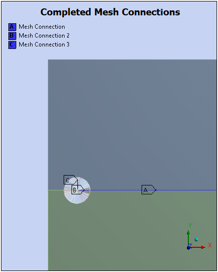
Right-click the Mesh Edit object and select Insert>Manual Mesh Connection.
Select the Edge selection option from the Graphics Toolbar.
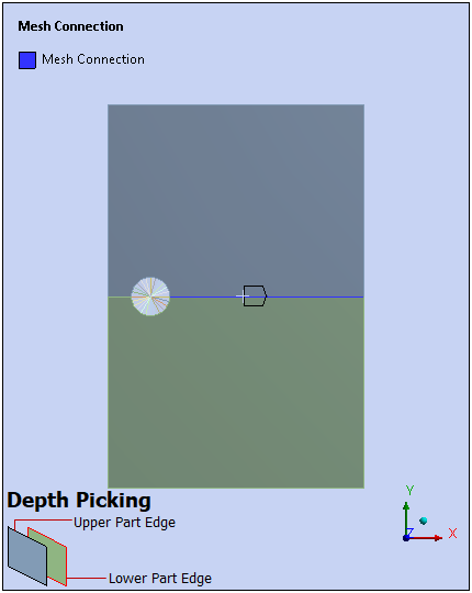
In the Geometry window, select the edge for the upper part (in contact with the lower part), and specify the edge for the Primary Geometry property, Click Apply.
In the Geometry window, select the edge for the lower part (in contact with the upper part), specify the edge for the Secondary Geometry property. Click Apply. Use the depth picking tool displayed in the Geometry window (illustrated below) to assist in your selection.
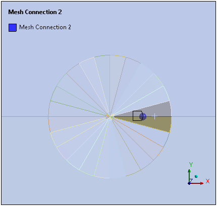
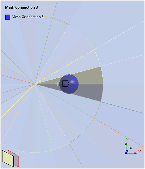
Using the above steps, create two more Mesh Connections to connect the edges of the desired mesh regions.
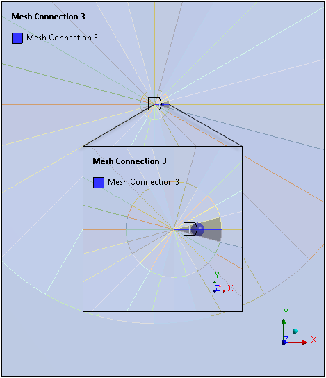
As illustrated below, the final mesh connection requires you to zoom in a great deal on the desired edges.
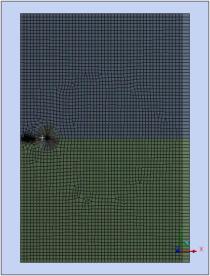
Right-click the Mesh Edit object and select Generate. This step generates the mesh connections and the overall mesh of the model.
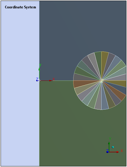
Right-click the Coordinate System object and select > .
Select the Vertex selection option from the Graphics Toolbar.
In the Geometry window, select the vertex in the middle of the left hand side of the structure. Specify this vertex for the Geometry property in the Details of the Coordinate System.
Select the Vertex selection option on the Graphics Toolbar.
Right-click the Model object and select > Named Selection.
In the Geometry window, select the vertex at the point of the crack front. Zoom in as needed.
Select the entry field of the Geometry property and click Apply. The Named Selection is created for the selected vertex.
Right-click the new Named Selection, select Rename, and enter
Crack_Frontas the name.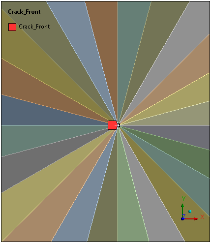
Right-click the Crack_Front Named Selection object and select .
Right-click the new Named Selection, select Rename, and enter
Crack_Nodeas the name.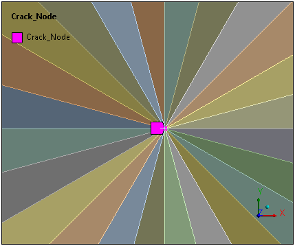
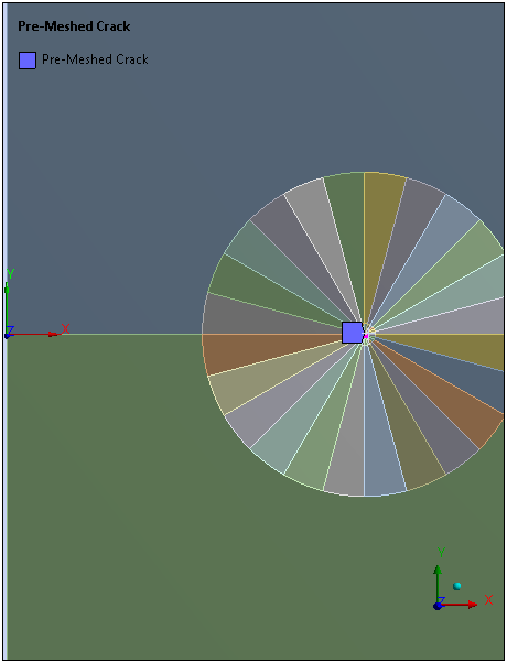
Right-click the Fracture object and select > .
Set the Crack Tip (Named Selection) property to Crack_Node.
For Coordinate System property, select the coordinate system you previously defined.
For Solution Contours property, set the value to 10.
Verify that the Unit system is set to: Metric (mm, kg, N, s, mV, mA). The Units drop-down menu is in the Tools group on the Home tab.
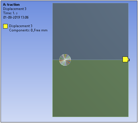
Right-click the Static Structural object and select > .
Select the Edge selection option from the Graphics Toolbar and select the bottom edge of the model.
In the Details view of the Displacement object, select the entry field of the Geometry property and click Apply.
Select the entry field of the Y Component property and select Tabular from the flyout menu.
Set the Independent variable property to X.
In the Tabular Data window, enter the evolution of Y Component against X coordinates:
In the first row (1), for Y[mm], enter
0.4.In the second row (2), for X[mm], enter
10and for Y[mm], enter0.48.
Set the X-Axis property to Time.
In the Tabular Data window, enter the evolution of scale against time: In the first row (1), for Scale, enter
0(make sure that the entry does not include an equals (=) sign).Repeat above steps to add an additional displacement for the top edge:
Selected Edge Independent Variable X: Tabular Data X-Axis Time: Tabular Data Top edge Evolution of Y Component against X coordinates
In the first row (1), for X[mm], enter
0and for Y[mm], enter0.7.In the second row (2), for X[mm], enter
10and for Y[mm], enter0.57.
Evolution of scale against time: In the first row (1), for Scale, enter
0(make sure that the entry does not include an equals (=) sign).
Right-click the Static Structural object and select > .
Select the Vertex selection option on the Graphics Toolbar.
Select the vertex on the right side of the specimen.
Select the Geometry property entry field and click Apply.
In the Details view, set the X Component property to
0.
Select the Analysis Settings object.
Under the Step Controls category, note that Substeps have already been defined because due to the plastic law the resolution will be nonlinear.
Under Fracture Controls category, make sure that the Fracture property is set to On.
Select the Solve option.
Define J Integral results.
Right-click the Solution object and select > .
For Crack Selection property, select Pre-Meshed Crack.
Right-click the Fracture Tool folder and select > .
Right-click the Fracture Tool object and select Evaluate All Results.
Select the Equivalent Plastic Strain result object.
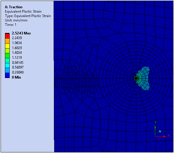
The plasticity is localized around the crack tip which is required for J-Integral calculation.
Select the J-Integral (JINT) result.
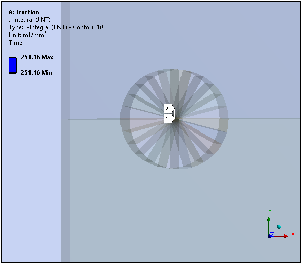
View the results and the Tabular Data for each result. The Tabular Data displays the J-Integral results at the crack front node for each integration contour.
Note that the results converge after several contour integrations. J-Integral results start converging when the integration contour is outside the plastic zone.
You have completed the fracture analysis and accomplished the overall objective for this tutorial.
Congratulations! You have completed the tutorial.