Introduction
The Shape Optimization option of the Optimization Type property enables shape optimization using mesh node relocations. As with the other optimization methods, this is a physics driven optimization based on a set of loads and boundary conditions provided by either a single preceding analysis or multiple preceding analyses.
Using this method, the application computes an optimal shape in the design domain that you can apply to a selected region of your model and that also includes specific design Objectives and Constraints.
Upstream System Recommendations
Review the following to properly prepare your upstream systems. Shape Optimization has the same capability as the Level Set method. Any differences are mentioned when necessary.
- Geometric Analysis
Review the Geometric Analysis topic in the Prerequisites and Requirements content in the Topology Optimization - Level-Set Based section for the supported Response Type and Response properties when performing a geometric analysis.
- Static Structural Analysis
Review the Configuring Static Structural Analysis topic in the Prerequisites and Requirements content in the Topology Optimization - Level-Set Based section for the supported Response Type/Response for the Objective Worksheet or a Response Constraint object to . Static Structural analyses supports the combination of force-based and displacement-based loading as well as thermal loading.
In addition, when specifying your upstream Static Structural analysis, note that any surface of the optimizable body that is scoped to boundary conditions (fixed displacements, loads, bonded contacts, etc.) must be defined in the Exclusion Region.
- Modal Analysis
This method supports Frequency (Eigenfrequency) as the Response/Response Type setting.
In addition, when specifying your upstream Modal analysis, note that you can control an eigenmode whose frequency always has the same ranking during the optimization process. If its ranking changes, the algorithm will face some difficulty.
- Manufacturing Constraint
For this analysis method, only the Member Size (Maximum) property is available. To properly represent the optimal shape, you should mesh your model such that Maximum Size of the Member Size is greater than four times the element average size.
Application Differences
Note the following when using the Shape Optimization method.
- Specifying the Mesh
This analysis method supports 3D tetrahedron solid elements only in the Optimization Region - all other element types are excluded.
Important: When specifying the mesh on your model, it is strongly recommended that you:
Always use a uniform mesh (homogeneous element size). This enables you to capture the design with the same precision everywhere on the model.
Make sure that you have a sufficiently fine mesh.
- Specifying Optimization Type
You use the Optimization Region object to select a region of your geometry on which to perform optimization as well as the optimization method to be used.
In order to scope the optimization regions using the method, you need to first generate the mesh.
Specify the Design Region. The properties of the Design Region category enable you to define the geometry as a Geometry Selection or a Named Selection. This is the region that you wish to optimize.
Specify the Exclusion Region. The properties of the Exclusion Region category enable you to specify a region (geometric entities or elements) to be excluded from optimization. You specify excluded regions using defined Boundary Conditions, Geometry Selection, or a Named Selection.
The surfaces scoped to boundary conditions (such as Fixed Support, Force, Bonded Contact, etc.) must be included in the scoping of the Exclusion Region.
Note: Bordering the scoping of your defined Exclusion Region is a "buffer zone." The area is a transition region where the deformation is less permissive. This enables a smoother result.
Set the Optimization Type property to . Specify the following additional properties as needed:
Move Limit Per Iteration: This property enables you to define how far each node can move at each iteration. It must be defined in length units, such as one element size. By default, this property is set to . Select the option to change the value.
Recommendation: Ansys recommends that you use a value smaller than the average element size and smaller than the Total Move Limit property setting.
Total Move Limit: This property enables you to define how far each node can move in total. It must be defined in length units, such as three element sizes. By default, this property is set to . Select the option to change the value.
Mesh Deformation Control: This property enables you to define how much the mesh can be stretched. It is an additional control to avoid element distortion. This unit-less value is a sort of penalty factor that ranges from 0 (no control) to 1.0. By default, this property is set to . Select the option to change the value.
Note: When you use the setting, a new value is computed that is based on the number of layers of elements in the mesh. As a result, the more layers you have, the more permissive the tuning. This means that the Total Move Limit will be higher, and the Mesh Deformation Control will be smaller.
- Specifying Results
This method supports Topology Density results. The Topology Density object is added automatically to the analysis system. You can add additional objects by selecting Topology Density from the Results group on the Solution Context tab or by right-clicking the Solution folder (or in the Geometry window) and selecting >.
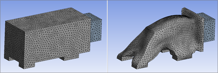
Here is an example of an optimized result.