


The Topology Optimization - Level Set method deals with the boundary of the shapes during the optimization process. It is a physics driven optimization that is based on a set of loads and boundary conditions provided by either a single preceding analysis or multiple preceding analyses. Using this method, the application computes an optimal shape in the design domain that can be applied to a selected region of your model and that can include specific design objectives and constraints. Here is an animated example of the Level Set topology optimization method.
The Level Set optimization workflow has some specific considerations as compared to the other methods, as described below. Use these topics in combination with the general workflow to ensure the proper completion of your analysis.
Prerequisites and Requirements
All upstream Static Structural and Modal analyses being used in your optimization problem must already be defined before you solve the optimization analysis
- Supported Mesh Elements
Only 3D elements are supported for optimization.
- Geometric Analysis
For the Objective and the Response Constraint objects, the Level Set method supports the following settings for the Response Type and Response properties:
Mass
Volume
Center of Gravity
Moment of Inertia
- Configuring Static Structural Analysis
Extend Compliance
For the Level Set method when you set the Response Type/Response for the Objective Worksheet or a Response Constraint object to Compliance, Static Structural analyses supports the combination of force-based and displacement-based loading as well as thermal loading. This context for Compliance is described by:

Where:
 is the total strain vector.
 is the thermal strain vector.
 is the elastic strain vector.
 is the stress vector.
 are the external loads (resp. volume and
surface).
are the external loads (resp. volume and
surface). are the reaction force and the prescribed
displacement.
are the reaction force and the prescribed
displacement.These formulas are equivalent and are based on the potential energy. The compliance is a self-adjoint response meaning that no adjoint problem must be solved. The compliance is always computed over the whole model.
Displacement-based Criterion (will be deprecated and fully replaced by the User Defined Criterion)
Context for displacement-based response:
For a singular node selection, the response =
 (
( -th node,
  -axis). You can define an upper limit for each
direction.
-axis). You can define an upper limit for each
direction.For multiple node selection, the response =
 (the average of the absolute displacement
along the k-axis).
(the average of the absolute displacement
along the k-axis).
Note: When you specify this type of Response Constraint, the Coordinate System property for the object is read-only and automatically set to . The application uses the for this setting.
Reaction Force Criterion (will be deprecated and fully replaced by the User Defined Criterion)
For a singular node selection, the response =
 (
( -th node,
  -axis). You can define an upper limit for each
direction.
-axis). You can define an upper limit for each
direction.For multiple node selection, the response =
 (the RF along the k-axis).
Note: When you specify this type of Response Constraint, the Coordinate System property for the object is read-only and automatically set to . The application uses the for this setting.
Review the Best Practices and Recommendations topic below for additional information for configuring your upstream analysis.
- Configuring Static Structural Analysis
Generalized Thermal Compliance
For the Level Set method when you set the Response Type/Response for the Objective Worksheet or a Response Constraint object to Thermal Compliance, Steady-State Thermal analyses supports the combination of Heat Flux, Heat Flow, and Temperature, Convection, and Internal Heat Generation. This context for Thermall Compliance is described by:

Where:
 is the gradient of the temperature.
 the isotropic thermal conductivity.
 the film coefficient and the ambient temperature
of the convection condition.
the film coefficient and the ambient temperature
of the convection condition. the internal heat generation.
 the heat flux.
This is based on the potential energy. The thermal compliance is a self-adjoint response meaning that no adjoint problem must be solved. The thermal compliance is always computed over the whole model.
- Configuring Modal Analysis
The Level Set method supports Frequency (Eigenfrequency) as the Response/Response Type setting. Review the Best Practices and Recommendations topic below for additional information for configuring your upstream analysis.
- Manufacturing Constraint Definition
The Level Set method supports the following Manufacturing Constraint Subtypes:
Member Size (Minimum or Maximum): To properly represent the optimal shape, you should mesh your model such that Maximum Size of the Member Size is greater than four times the element average size.
Pull Out Direction: You can further define the Direction for this constraint: (default), , or .
Note: The moldability of the part could be lost during the optimization process.
AM Overhang Constraint: This constraint enables you to further define the Build Direction and Overhang Angle.
Best Practices and Recommendations
Review the following suggestions when performing this analysis.
Mesh Specifications
When specifying the mesh on your model, it is strongly recommended that you:
Always use a uniform mesh (homogeneous element size). This enables you to capture the design with the same precision everywhere on the model. However, in the presence of thin regions, it may be necessary to refine the mesh locally in order to get at least three or four layers of elements.
Make sure that you have a sufficiently fine mesh. If the final design shows geometric features as thick as an element size, it means that the mesh was not fine enough, as illustrated here.
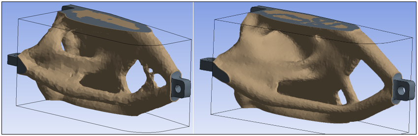
This illustration displays 238,000 tetrahedrons on the left and 950,000 on the right. The feature on the left is very thin (one element size) and reaches the limit of the Level Set capability to properly capture the design. The finer mesh on the right provides an improved design.
Configuring a Static Structural Analysis
When specifying your upstream Static Structural analysis, note the following:
A minimum stress problem can be realized by a void design (no material) if there is no stiffness constraint - if there is no mass, there is no stress. Therefore, Ansys recommends that you use stress criterion in combination with a stiffness criterion (nodal displacement, compliance, etc.).
It is strongly encouraged that you specify an "exclusion zone" around the loading conditions (surface or node-based).
If your solution experiences disconnected clamped parts, it may be a result of the optimization aiming to optimally distribute an amount of material. The algorithm sometimes chooses to save material by disconnecting clamped parts and/or to reinforce others. This characteristic of optimization is useful in order to identify useful and/or otherwise impractical fixed parts.
Configuring a Modal Analysis
You can control an eigenmode whose frequency always has the same ranking during the optimization process. If its ranking changes, the algorithm may face some difficulty.