The optimization analysis offers a Optimization Type. This method enables you to compute an optimal variable density lattice distribution in your geometry. Use the following lattice specific topics in combination with the general workflow to ensure the proper completion of your analysis.
Lattice Optimization Limitations
In addition to the Topology Optimization - Density Based method limitations, the lattice optimization has the following additional limitations. Lattice optimization does not support:
Nonlinear Contact
Modes with an Eigenfrequency equal to zero (based on an upstream Modal analysis)
Thermal Loads
Export Topology (STL file)
Local Von-Mises Stress Constraint
Reaction Force Constraint
Criterion
Member Size Manufacturing Constraint
Pull Out Direction
Extrusion
AM Overhang Constraint
For the Octahedral 1 and Octahedral 2 lattice structures, note the following material property limitations:
A Poisson ‘s Ratio value greater than 0.32 can cause the interpolated material properties to become inaccurate.
A low Density value (< 0.05) can generate a negative Young's Modulus value.
Define Lattice Type, Density, and Cell Size
When you specify the design and exclusion regions for your lattice optimization, you need to then define the following lattice specific properties.
|
Category |
Properties/Options/Description | ||||||||||||||||
|---|---|---|---|---|---|---|---|---|---|---|---|---|---|---|---|---|---|
|
Lattice Type |
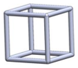
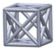
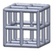
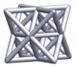
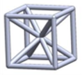
Specify the Lattice Type as one of the following:
| ||||||||||||||||
|
Minimum Density |
This property specifies a minimum density in order to avoid lattice structures that are too thin. | ||||||||||||||||
|
Maximum Density |
This property specifies a maximum density. The element will be considered as full for densities higher than the Maximum Density. | ||||||||||||||||
|
Lattice Cell Size |
The value of this property specifies the lattice cell size to be used when rebuilding the lattice geometry for printing. |


Specifying Constraints
For this analysis, the:
Response Constraint object supports (default) or , , , and .
Design Constraint object supports the Symmetry and Cyclic Repetition constraints.
Defining Results
Similar to the optimization results (Topology Density and Topology Elemental Density), lattice optimization supports Lattice Density and Lattice Elemental Density results. These results produce nodal averaged results and element-based result values. A Lattice Density result object is inserted automatically. You can add additional objects by selecting Lattice Density or Lattice Elemental Density from the Result group on the Solution context tab or by right-clicking the Solution folder (or in the Geometry window) and selecting > /.
- Result Display Feature
A lattice analysis automatically inserts a as a child object of the Solution Information object that enables you to view the optimization of the model during the solution.
- Results Display Limitations
These result types do not support some of the display options available from the Geometry drop-down menu on the Result Context tab, including , , and .
Creating the Lattice Geometry
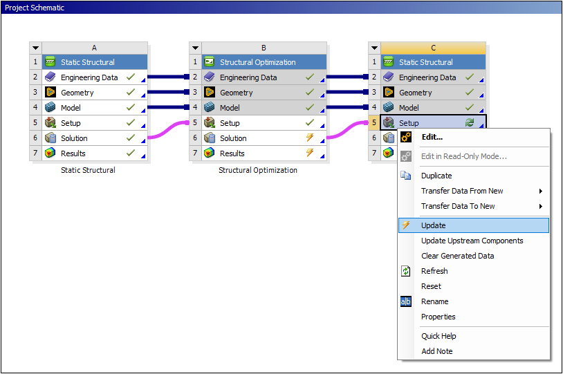
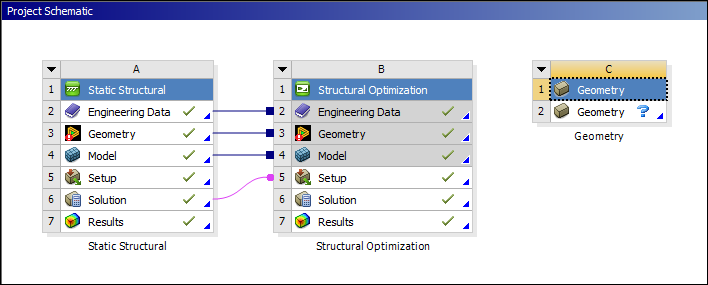
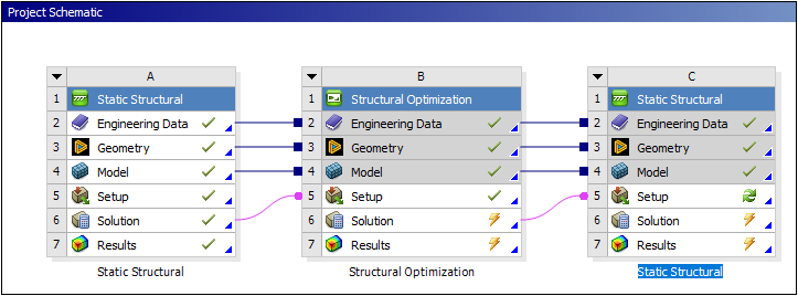
To make the optimized results available to a downstream geometry system, you need to create the new system on the Workbench Project Schematic and link the cell of your lattice optimization analysis to the Geometry cell of a new downstream system, either a Geometry component system or the Geometry cell of another analysis system. An example of this configuration is illustrated below.
The lattice type, cell size, and density information are automatically transferred when linking a lattice optimization analysis to a Geometry system. Opening your new lattice geometry in the Ansys SpaceClaim application enables you to further modify aspects of your geometry.
Procedure
From the Workbench Project Schematic, create a new downstream Geometry system, as illustrated below.
Link the cell of your lattice optimization analysis to the Geometry cell of the downstream system.
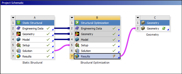
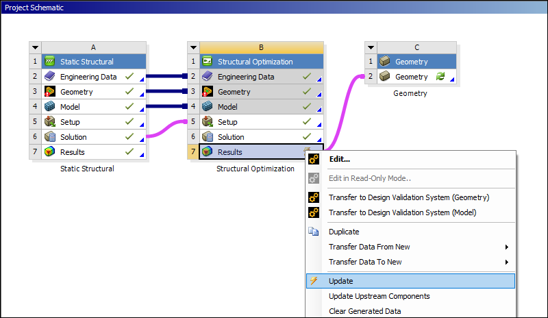
Right-click the cell of your lattice optimization analysis and select .
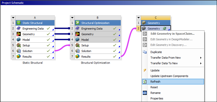
Right-click the cell of the downstream system and select .
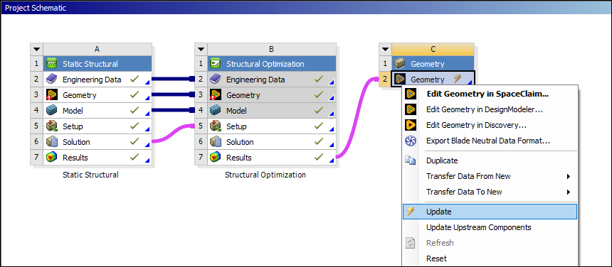
Right-click the cell of the downstream system and select .
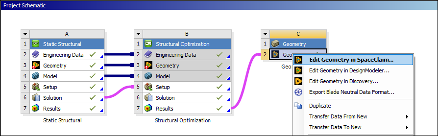
Open SpaceClaim from the cell of the downstream system.
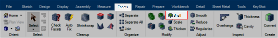
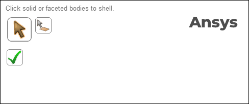
In SpaceClaim, select Shell tool from the Facets tab.
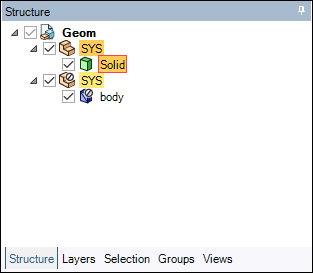
From the Shell Options tool, 1) choose as the Infill type, and then 2) select the Solid body in the structure tree, and then 3) select Use Density Attributes. The Lattice Shape from the drop-down menu is automatically chosen. This includes the lattice type you specified in the optimization analysis in Mechanical.
Note: Using the Select Faces or Facets tool (
 ) from the
design window, you can choose to selectively exclude faces from the
original body from this outer shell. This enables the lattice infill to
extend all the way to the boundary of the part on that face.
) from the
design window, you can choose to selectively exclude faces from the
original body from this outer shell. This enables the lattice infill to
extend all the way to the boundary of the part on that face.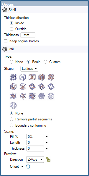
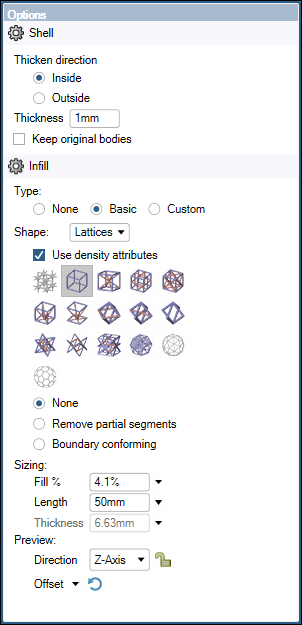
A green check mark in the design window verifies the operation. The density distribution from the lattice optimization is now mapped onto the body and a faceted body is generated.
Lattice Validation with a Homogenization Model
For a Lattice Optimization analysis, the steps to create a downstream validation are slightly different than for the other optimization methods available in the application.
Note: For the upstream system, the Output Controls property Export Knockdown Factor must be set to . This is the default setting.
- Duplication
When you use the option on the Solution cell, you include all (loading, results, etc.) objects defined in the upstream system.
Right-click the Solution cell of the upstream system and select . A new system is placed into the schematic. This new system includes all environmental conditions defined in the upstream system, such as loading conditions or results.
Drag and drop the Solution cell of the Structural Optimization analysis onto the Setup cell of the new system. The application properly links the systems together.
Right-click the Setup cell of the new system and select . Your new system is ready for a validation analysis.
An animation of these steps is illustrated below.
- Transferring Data
You can also use the system option . When used, none of the environmental conditions defined in the upstream system, such as loading conditions or results are included in the new system. The steps to use this method are described below.
Right-click the Solution cell of the Structural Optimization analysis and select > Analysis System type.
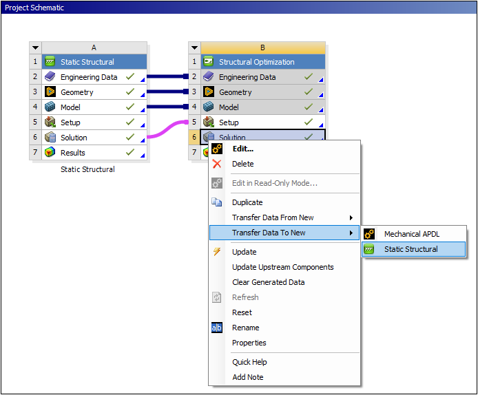
A new system in inserted and is linked accordingly.
Right-click the Setup cell of the new system and select . Your new system is ready for a validation analysis.