


Mistuning on Cyclically Symmetric Structures
Small mistuning effects (on the order of a few percent) may be included in the analysis by introducing blade-to-blade variations in the stiffness (frequency) of each blade.
Mistuning is based on the Component Mode Mistuning methodology (see Mistuning in the Mechanical APDL Theory Reference), which requires the elements making up the blade and the interface nodes between these elements and the rest of the sector model to be in an element and nodal component (CM) respectively. Use the CYCFREQ,BLADE command option to provide this information, as well as how many blade modes to include and their frequency range.
For blades with shrouds, the nodes on the shroud boundaries should also be in the node component (if the shroud interfaces are modeled as stuck).
The mistuning parameters are provided in a parameter array of size Ν×1, where
Ν is the number of blades. Each row represents the deviation in stiffness of each blade
δn from the nominal value [Κ0] used
in the modal cyclic symmetry analysis. Equivalently, the stiffness deviation,  , may be expressed in terms of
each blade's natural frequency deviation squared,
, may be expressed in terms of
each blade's natural frequency deviation squared,  , where
ω is the nominal (tuned) blade frequency and ωn is
the mistuned frequency of blade n.
, where
ω is the nominal (tuned) blade frequency and ωn is
the mistuned frequency of blade n.
It should be noted that the stiffness deviation is equivalent to  where
[Ε] denotes the Young's modulus only in the case where there are no
prestress effects. In the presence of prestress, the nominal stiffness
[Κ0] is updated, and then mistuning is
applied.
where
[Ε] denotes the Young's modulus only in the case where there are no
prestress effects. In the presence of prestress, the nominal stiffness
[Κ0] is updated, and then mistuning is
applied.
You may also mistune each of the individual blade frequencies, in which case the
provided array parameter would be Ν×Μ, where each column is for the Μ
blade frequencies (from the CYCFREQ,BLADE specification), and each entry
corresponds to that blade's frequency deviation squared,  , where the subscript
ι refers to the ιth frequency of blade n
(such that the array location (n,ι) contains
this value).
, where the subscript
ι refers to the ιth frequency of blade n
(such that the array location (n,ι) contains
this value).
Use the CYCFREQ,MIST command to provide this array name.
Mistuning Load Definition
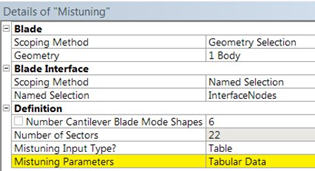
Pick the blade and blade interface. If shared topology is used, the blade interface should be selected automatically.
The number of blade modes to include in the CMS reduction. Refers to the Mechanical APDL command CYCFREQ,BLADE,,,value.
The number of sectors is automatically populated and gives the number of mistuning values to be input.
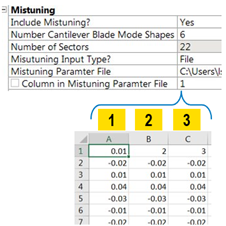
Mistuning can be entered manually, imported from a .csv file, or be randomly generated.
- File
Select a .csv file. This file must contain a set of mistuning parameters per column. The Column in Mistuning Parameter File setting defines which columns will be read in the file. Using that setting, you can parameterize the mistuning parameter for each blade. The number of rows in the file must be equal to the number of sectors.
- Random
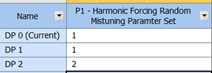
Choose between (Gaussian) or distribution. A new set of random mistuning values will be generated every time the Random Mistuning Parameter Set value is changed. You can perform several analyses using the same random mistuning value. The random mistuning values are saved for later review.

Understanding Changes to ds.dat
Including the mistuning load modifies the ds.dat file of the Harmonic system accordingly to include the mistuning definition.
The blade elements and interference nodes are defined according to the scoped geometry.
*DIM,KMIST,ARRAY,BM,1 is included, where BM is the number of sectors defined.
KMIST defines the mistuning parameters for each blade.
CYCFREQ,BLADE,ACTInterfaceNodes,ACTBladeElem,BN defines blade element component and interface nodes, where BN is the number of cantilever beam shapes.
CYCFREQ,MIST,K,KMIST defines stiffness mistuning.