VM-LSDYNA-SOLVE-026
VM-LSDYNA-SOLVE-026
Radial Displacement of a Pinched Cylinder
Overview
| Reference: |
Cook, R. D. (1981). Concepts and applications of finite element analysis. (2nd ed.). John Wiley and Sons. pp.284-287. Takemoto, H. & Cook, R.D. (1973). Some modifications of an isoparametric shell element. International Journal for Numerical Methods in Engineering, 7 (3). |
| Analysis Type(s): | Analysis Type |
| Element Type(s): | Element Type |
| Input Files: | Link to Input Files Download Page |
Test Case
A thin-walled cylinder is pinched by a force F at the middle of the cylinder length, shown in Figure 98. Determine the radial displacement 𝛅 at the point where F is applied. The ends of the cylinder are free edges.
This problem is also presented in test case VM6 in the Mechanical APDL Verification Manual.
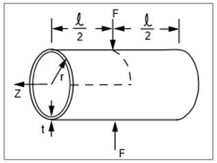
| Material Properties | Geometric Properties | Loading |
|---|---|---|
|
E = 1.05e7 psi v = 0.3125 |
r = 4.953 in t = 0.094 in l = 10.35 in | F = 100 lb |
Analysis Assumptions and Modeling Notes
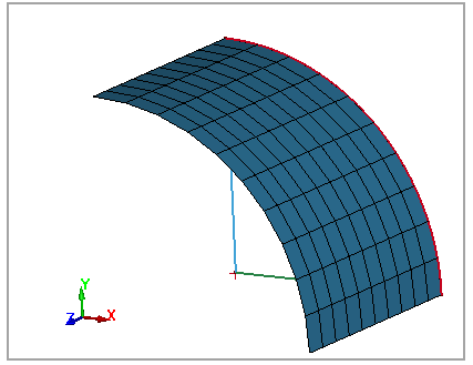
A one-eighth symmetry model is used. One-fourth of the load is applied due to symmetry with card *LOAD_NODE_POINT. The thin-walled cylinder is modeled with shell element elform 2 and 16. An implicit analysis is performed to determine displacement where the load is applied.
The 1/8 thin-walled cylinder model mesh is shown in Figure 99.
Results Comparison
| Results | Target | LS-DYNASolver | Error (%) |
|---|---|---|---|
| Deflection (in) elform = 2 | 0.1139 | 0.1158 | 1.67 |
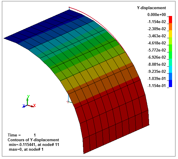
| Deflection (in) elform = 16 | 0.1139 | 0.1154 | 1.32 |
The deformed cylinder is shown in the following contour plot, Figure 100.