VM-LSDYNA-SOLVE-025
VM-LSDYNA-SOLVE-025
Laterally Loaded Tapered Support Structure
Overview
| Reference: | Crandall, S.H. & Dahl, N.C. (1959). An introduction to the mechanics of solids. McGraw-Hill Book Co. p.342. |
| Analysis Type(s): | Implicit Analysis |
| Element Type(s): | Shell |
| Input Files: | Link to Input Files Download Page |
Test Case
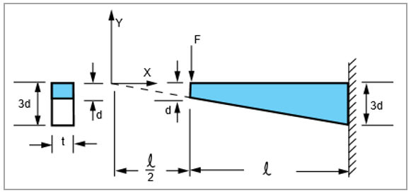
A cantilever beam of thickness t and length 𝓁 has a depth d which tapers uniformly from d at the tip to 3d at the wall. It is loaded by a force F at the tip, as shown. Find the maximum bending stress at the fixed end of the beam.
This problem is also presented in test case VM5 in the Mechanical APDL Verification Manual.
| Material Properties | Geometric Properties | Loading |
|---|---|---|
|
E = 3e7 psi ν = 0 |
t = 2 in d = 3 in 𝓁 = 50 in |
F = 4000 lb |
Analysis Assumptions and Modeling Notes
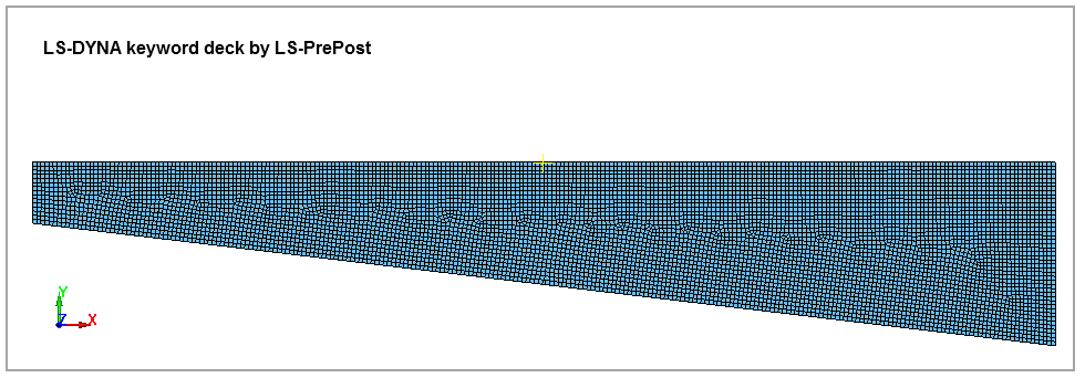
The tapered cantilever beam is modeled with shell element elform 1, 12, and 16. The nodes at the fixed end of the beam are constrained in x, y, z, rx, ry, and rz directions. And a point load is applied at the free tip node of the beam with *LOAD_NODE_POINT. An implicit analysis is performed to find out the maximum x stress at the fixed end, and the results are compared among different element formations.
The beam is meshed with a 0.2 in element size, as shown in Figure 97.