VM5
VM5
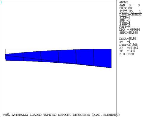
Laterally Loaded Tapered Support Structure
Overview
Test Case
A cantilever beam of thickness t and length
 has a depth which tapers uniformly from d at the
tip to 3d at the wall. It is loaded by a force F at the tip, as shown.
Find the maximum bending stress at the mid-length (X =
has a depth which tapers uniformly from d at the
tip to 3d at the wall. It is loaded by a force F at the tip, as shown.
Find the maximum bending stress at the mid-length (X =
 ) and the fixed end of the beam.

| Material Properties | Geometric Properties | Loading | ||||||
|---|---|---|---|---|---|---|---|---|
|
|
|

The PLANE183 model uses the same node numbering at the element corners as the PLANE182 model and has additional midside nodes added to all elements.
Analysis Assumptions and Modeling Notes
Two different solutions are obtained. The first solution uses lower order PLANE182 elements and the second solution uses higher order PLANE82 elements. The 2 inch thickness is incorporated by using the plane stress with thickness option. Poisson's ratio is set to 0.0 to agree with beam theory.