


The interface writes coordinate, connectivity and boundary condition information in the Patran-based Polyflow format. The following Patran packets compose the input file created with this interface:
Packet 25: Title Card
Packet 26: Summary Data
Packet 01: Node Data
Packet 02: Element Data
Packet 06: Distributed Loads
Packet 07: Node Forces
Packet 99: End of Neutral File
Creating the Polyflow Input File
The translator writes the Polyflow Neutral File Version 2.4 using an unstructured domain file and its boundary condition file. Select Polyflow in the Output Solver drop-down list and click . Then select the  Write input option in the Output tab. A window will open to allow the specification of the files to be translated into the Polyflow format. An existing unstructured mesh file must first be selected.
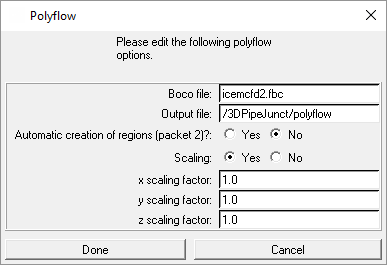
Specify the following:
the name of the boundary condition file (default is configuration/parts_mesh/mesh/boco)
the name of the Polyflow input file (default is configuration/parts_mesh/transfer/configuration.poly)
the scaling factor for the coordinates in the geometry file (optional)
The interface generates the Polyflow file located in the Transfer Shell. You may open a shell window in this directory by selecting the menu items "Utility" and "Transfer Shell".D
Defining Boundary Conditions for Polyflow
In MULCAD the boundary conditions are defined in the "Unspec. Bound. Cond." menu. In the DDN-Mesher Interface, the "general bound. cond." menu is used. Refer to the General Remarks section for more details. For P-CUBE, the NAME field and ID # icon are used to prescribed the Polyflow boundary conditions. Three types of boundary conditions/properties are available for Polyflow: distributed loads, nodes forces and PID numbers.
Distributed Loads: —
MULCAD          DDN-Mesher      P-CUBE
------          ----------      ------
1.FLAG          1.string1       NAME field      Enter the word DISTR
2.NR            3.integer       ID # icon       Enter the load ID number
The element numbers and their load ID are written out in Packet 6. The boundary condition DISTR is only recognized on subfaces for a 3D model and on edges for a 2D model.
Node Forces: —
MULCAD          DDN-Mesher      P-CUBE
------          ----------      ------
1.FLAG          1.string1       NAME field      Enter the word NODE
2.NR            3.integer       ID # icon       Enter the node ID number
The node numbers and their load ID are written out in Packet 7. The boundary condition NODE is available on subfaces, edges and vertices for a 3D model and on edges and vertices for a 2D model.
Element PID: —
MULCAD          DDN-Mesher      P-CUBE
------          ----------      ------
1.FLAG          1.string1       NAME field      Enter the word PID
2.NR            3.integer       ID # icon       Enter the PID number
The element PID are written out in Packet 2. They must be defined on domains for a 3D model and on subfaces for a 2D model. Their default value is 1.
Limitations
It is assumed for the moment that there is no need to define boundary conditions on interfaces since Polyflow expects the load sets to be defined on the boundaries of the domain only.
Polyflow does not allow a mix of 2D and 3D elements in the same model. The type of elements recognized by the Polyflow Translator are:
in 2D:
3 or 6 points triangle
4 or 9 points quadrilateral
in 3D:
4 or 10 points quadrilateral
8 or 27 points hexahedral
6 or 18 points wedge pentahedral
5 or 14 points pyramidal pentahedral