


| Data Format | CGNS Version 4.3 (ADF / HDF) |
| Type of mesh | unstructured or structured mesh |
| Dimension | 2D and 3D |
The Ansys ICEM CFD - CGNS output interface creates a CGNS file in accordance with the SIDS. It uses the CGNS mid-level-library endorsed by the CGNS Steering Committee to create the file. This interface supports both structured and unstructured mesh translation.
Creating the CGNS File
The CGNS output interface can be invoked from the Ansys ICEM CFD main window. Select CGNS in the Output Solver drop-down list and click . Then select the  Write input option in the Output tab. A window will open to allow the specification of the files to be translated into the CGNS format. An existing unstructured mesh file or a set of structured mesh files must first be selected.
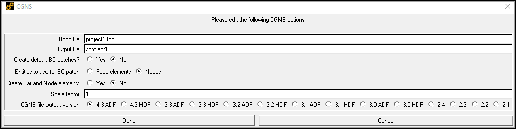
In addition, the output interface requires the boundary conditions file, and for structured mesh input, the topology file. It offers options for naming the CGNS file and to select the automatic creation of boundary condition patches. You can set the Scaling factor for the coordinates in the CGNS file, which can be used to transform the type of units by which the mesh is measured (for example, setting the Scale factor to 1000 would change the scale from meters to millimeters). For unstructured mesh input, you have the additional option to select whether the boundary condition patches are defined using nodes or face elements. Default names for the Ansys ICEM CFD input files and the CGNS file are given. These can be modified as necessary. The interface generates the CGNS file in the current project directory.
Note: When writing the CGNS file, the maximum number of elements in a part multiplied by the number of nodes per element cannot exceed 2 billion.
For linear Hexa meshes, the maximum number of elements in a part should not exceed 250 million.
For linear Tetra meshes, the maximum number of elements in a part should not exceed 500 million.
To export meshes with parts comprising a large number of elements, ensure that larger parts are split into smaller parts within these limits.
Connectivity
This translator supports 1-1 connectivity and periodic interfaces.
Defining Boundary Conditions (Optional)
After generating the mesh, and prior to running the translator, boundary conditions can be defined. Select the  Boundary conditions option in the Output tab. The Part boundary conditions window appears, allowing you to set boundary conditions. Two boundary conditions types are available: BCType and BCDataSet. Note however that BCDataSet in a subset of BCType in CGNS and therefore cannot be defined by itself. A boundary condition patch can either have a BCType alone, or a BCType with one or more BCDataSets.
BCType
The boundary condition types (BCType) are defined in the SIDS. They identify the equations that should be enforced at a given boundary. To define a boundary condition type, select a boundary family (face in 3D, edge in 2D) and one of the BCType options in the provided list.
BCDataSet
Boundary condition data sets are used to define the BCTypeSimple, and one or more global boundary condition data. When boundary condition data sets are specified, the boundary condition type must be selected. This can be either Dirichlet or Neumann. Only uniform boundary condition data are supported by the translator; the data given are applied to the entire boundary condition patch. The list of variables corresponds to the standardized Data-Name Identifiers found in Annex A of the SIDS. In general, BCTypeSimple is the same as BCType and no more than one BCDataSet is required. In some particular cases however, the boundary condition type can be flow dependent. In such case, BCTypeSimple differs from BCType. The SIDS defines these special cases as "compound boundary conditions". For example, an inflow boundary where the flow goes from subsonic to supersonic would require a compound boundary condition. In such case, two BCDataSets would be added, each with a different BCTypeSimple:
with BCTypeSimple = BCInflowSubsonic
with BCTypeSimple = BCInflowSupersonic
For more details on the use of compound boundary conditions, refer to the SIDS.
3D Elements Groups for Unstructured Grids
The CGNS standard does not provide a specific method for grouping elements. The translator offers this feature by creating a DataArray_t node under Zone_t/DiscreteData_t. This DataArray_t node is named PID and contains on array of integers for the pid of each element. Each element's PID is set to its family ID number. The order in which the element's PIDs are listed follows the same order as the global element numbering under Element_t.