| Solver | Ansys Fluent |
| Type of mesh | unstructured mesh |
| Dimension | 2D and 3D |
The Ansys Fluent interface creates a Fluent or Fluent Meshing mesh file from an unstructured mesh, with the following grid sections:
| Section | Index |
| Comment | 0 |
| Dimensions | 2 |
| Nodes | 10 |
| Cells | 12 |
| Faces | 13 |
| Periodic Shadow Faces | 18 |
| Zone Section | 39 |
The mesh file can be written in ASCII or binary format.
Note: The Fluent output interfaces are separate executables that operate on project files that have been saved to disk. This means you will need to save the project, particularly the mesh, part boundary conditions, and/or properties files before sending output to the solver. If your mesh is large and you are concerned about memory limitations and do not want the mesh loaded twice into memory (the editor and the output interface), you can then unload the mesh and proceed with the output based on the saved mesh file.
Creating the Ansys Fluent Input File
The translator writes the Ansys Fluent input file using an unstructured mesh file and its boundary condition file. To create the Ansys Fluent file, select Ansys Fluent in the Output Solver list and click . After generating the mesh, boundary conditions can be defined. Supported boundary conditions are:
| Volume | fluid, porous, solid |
| Surface | axis, fan, interior, mass-flow-inlet, outflow, periodic, porous-jump, pressure-inlet, pressure-far-field, pressure-outlet, radiator, symmetry, velocity-far-field, velocity-inlet, wall |
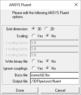
Select the  Write input option in the Output tab. A window will open to allow the specification of the files to be translated into the Ansys Fluent format.
Specify the following:
the grid dimension
the scaling factor for the coordinates in the geometry file (optional)
ASCII or binary output
ignore couplings (yes or no)
the name of the boundary condition file
the name of the Ansys Fluent file
Creating the TGrid Input File
The translator writes the TGrid input file using an unstructured mesh file and its boundary condition file.
Note: TGrid is the same as Fluent Meshing and supports only surface mesh.
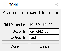
To create the TGrid file, select TGrid in the Output Solver list and click . Select the  Write input option in the Output tab. A window will open to allow the specification of the files to be translated into the TGrid file.
Specify the following:
the grid dimension
the name of the boundary condition file
the name of the Fluent Meshing file


