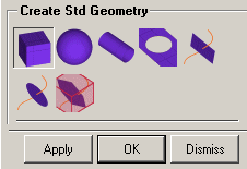
 The Standard Shapes option creates standard geometrical shapes. The following options are available.
- Box

There are two methods to creating a box.
Specify
Define the lengths of the box sides in the X, Y, and Z directions and select the point for the box origin. For example, an X Y Z size of "1 1 1" and Box Origin "0 0 0" will result in a box with sides of length one, with its origin at the coordinates (0,0,0).
Entity bounds
Creates a bounding box around the selected entities. The X, Y, and Z lengths of the box can be scaled by the specified factor.
Adjust min/max values
If this is enabled, the minimum and maximum coordinate values of the box will be displayed. To create a new box, you can change any of these values and click Apply.
- Sphere from 2 points

Radius
If enabled, then the radius length can be defined.
Start/End angles
The angles (in degrees) are measured from the normal of the center plane of a sphere (the pole). An arc from the Start angle to the End angle will be rotated 360 degrees. For example, a Start angle of 0 and an End angle of 90 will result in the top half of a sphere.
Locations
The application prompts you to select two locations on the screen. The first is the center of the spherical surface, and the second defines the normal of the center plane (pole). If Radius is toggled OFF, then the second point will determine the length of the radius as well.
- Cylinder

Radius1 and 2
Specify the Radius1 and Radius2 of the respective base circles of the cylinder.
Base1 and Base2
If enabled, the respective bases circles will be created.
Two axis Points
Select two points to define the axis of the cylinder.
- Drill a Hole

Surface
Select the surface in which the hole is to be drilled.
Remove Hole
Enable if you wish to replace a current hole. This will allow you to select a curve (hole) which will be deleted and replaced with the new specified hole. If no curve is selected, the last hole created will be removed.
Note: If Remove Hole is enabled, and the selected curve is a feature and not a hole, that curve will still be removed.
Radius
Enter the radius length.
Location
Select the point of the center of the hole.
- Plane normal to curve

Side
Enter the length of the side for the uniform surface.
Location on curve
Select the location on the curve at which the normal plane is to be created.
Curve parameter
Instead of selecting the location on the curve, the distance along the curve can be specified.
- Disc normal to curve

Radius
Enter the radius length for the disc.
Location on curve
Select the location on the curve at which the disc is to be created.
Curve parameter
Instead of selecting the location on the curve, the distance along the curve can be specified.
- Trim normal to curve

Creates a plane normal to the selected curve and trims this plane with the selected surface(s). The plane will only be created if the intersection curve of the plane to be created and the selected surfaces is a closed loop.
- Surfaces
Select the surface that will be used to trim the newly created plane.
- Location on curve
Click the selection icon and select the location on the curve where the plane will be created. Click to create the plane.
- Curve parameter
To specify the location on curve using the curve parameter (between 0 to 1), select any location on the curve, enter the curve parameter, and click .
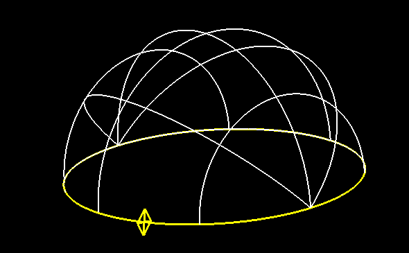
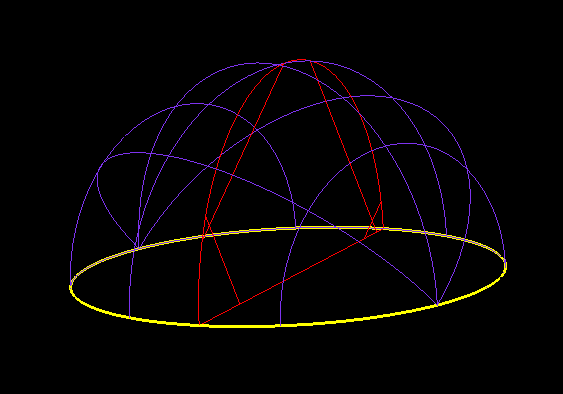
In the example in Figure 197: Surfaces and Curve Selection, the top and bottom surfaces of the hemisphere are selected. And the point on the curve is selected for the creation of the plane. In the second figure, note that the created plane's intersection with the selected surfaces creates a closed loop.


