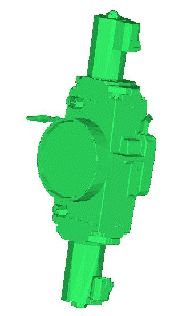
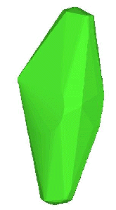
 The Geometry Simplification option creates a set of faceted surfaces wrapped around the selected geometry, including surfaces, curves, or points. The original geometry is retained.
Convex Hull Method
There are 3 methods to choose from, single hull, interactive split and regular split.
For faceted data, it may be helpful to first merge all surfaces, and then merge all nodes of the concatenated surface within a tolerance. This will reduce the computation time.
There are three different options for the Convex Hull Method.
Single Hull
Creates a crude wrapped surface around the actual selected surfaces as shown in Figure 190: Single Hull Option.
Interactive Splits
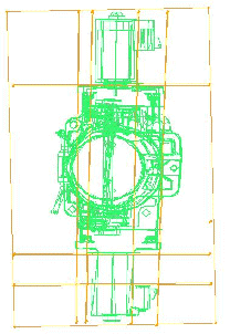
In this method, the application prompts you to draw lines representing split planes. These planes do not need to be aligned with the global axis.
Uniform Splits
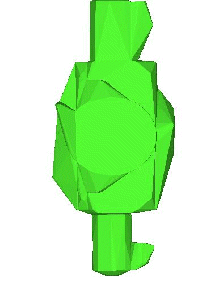
In this method, a uniformly spaced grid of planes is used to segment the actual selected surfaces and a hull is then created around each segment. You must define the number of planes in the X, Y and Z directions. The planes (X, Y, Z axes) are either aligned to the global coordinate system (the Model option) or to that of the current Screen orientation, with the X-axis horizontal, Y-axis vertical, and Z-axis normal to the screen. A large number of planes will create a three-fold large number of segmented components, which may take a long time to process for complicated geometry. For example, a 10 x 10 x 10 grid will create 1000 components.
- Coarsen before Creating Hull
Faceted entities will be coarsened to reduce the triangulation and the processing time.
- Tolerance
Edges of the faceted triangles will be merged within the tolerance setting during the coarsening process. The value is an absolute setting.
- Remove Interior Faces
If enabled, the interior hull surfaces of segments created by the Interactive Splits or Uniform Splits methods will be removed. Only the outer shell formed around the selected surfaces will be retained.
- Hull for Each Part
Each segment created after a hull is built around a component will be put into a new part.
Cartesian Shrinkwrap
Wraps a complicated geometry using a Cartesian staircase mesh. The mesh is then locally projected and smoothed to get a simplified representation of the geometry.
Note: For the resulting mesh, if surfaces mesh sizes are set, then this will override the global max size value.
The following options are available:
- Max. cell size
The size of the facets of the shrinkwrap. This should be set to just a little larger than the largest hole you want to ignore.
- Num. of smooth iterations
Number of smoothing iterations to be performed.
- Surface projection factor
Factor from 0 to 1 that determines how well the shrinkwrap will project to the geometry after the staircase mesh is created.
- Part for envelope
Determines the Part that the Shrinkwrap will be created in. You can select an existing part, use the screen select to select a part on the screen, or type in a new part name in the field. The inherited option will place the shrink wrapped mesh in the same part as the geometry that it lays on, this is determined by a normal vector ray calculated from each facet.
- Wrap part by part
Creates an individual shrinkwrap per part.
- Active parts only
If enabled, then shrinkwrap will only be applied to the active parts.
- Create Geometry
If disabled, the wrap produced is mesh. If enabled, the wrap is automatically converted into a faceted geometry. When used in conjunction with the inherited option for Part for envelope, the Part names for the new geometry entities will be the inherited names followed by "_WRAP" to differentiate them from the original geometry.
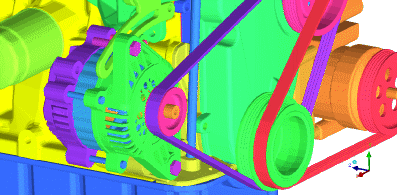
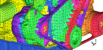
Figure 193: Engine Geometry shows an engine geometry. Such engine geometries may have much more detail than is needed for an under hood analysis and can be simplified. The geometry can be wrapped to close holes, combine parts, and generally simplify the data as shown in Figure 194: Wrapped Engine.
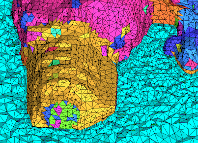
The wrapped surface mesh can then be used with a bottom-up tetra method to generate a volume mesh or converted to faceted geometry as described.


