 The Multiblock
smoother is used to obtain smooth grid lines. It is specially optimized
for blade configurations. The mathematical basis is that an elliptical
differential equation of the form
 , where
is the "control function",
will be solved. It can be proved that by using the elliptical operator
, smoothness of the mesh will be achieved. The control
function
will be specified so that the smoothed mesh will
obtain certain characteristics, such as orthogonality and layer height
of the first layer.
The Multiblock smoother can also constrain nodes in one dimension and smooth nodes in the other dimensions in order to improve mesh quality. This is useful in turbine blade analysis for the inlet and outlet surfaces. While smoothing, the blade surfaces are frozen to maintain geometric location. Previously, the inlet and outlet would be frozen, thereby freezing the ends of the periodic sides, and thereby limiting the smoother. By constraining nodes in one dimension, the inlet and outlet are constrained axially, maintaining their distance from the blade as well as their periodicity. However, the nodes can be smoothed in the other dimensions, thereby allowing the smoother more flexibility.
For all other mesh types, the options for Smooth Mesh Globally will be displayed.
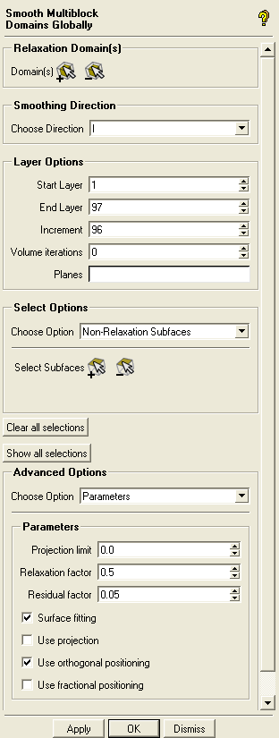
The following parameters are available when a multiblock mesh is loaded:

- Relaxation Domain(s)
click the appropriate icon to select or deselect domain(s) to be smoothed.
- Smoothing Direction
- 3D
smoothes the mesh in all directions.
- I, J, or K
allows you to select the smoothing direction.
- Layer Options
This smoother works by smoothing planes and then interpolating the smoothing between the layers. The model is reduced to a single block high and the layers are the mesh indices from one side to the other along the smoothing direction. You need not smooth every plane. In models with very little twist, selecting the first and last plane is sufficient. If a model (such as a compressor blade) has more twist, it may be advantageous to smooth the first and last, as well as a few layers between.
- Start Layer, End Layer
the first (usually 1) and last (usually the total number of layers) to be smoothed. These form the ends of the smoothed volume and are usually setup automatically.
- Increment
allows you to add smoothing planes between the first and the last planes. For instance, if you have 26 planes, you could have an increment of 5, which would mean the 6th, 11th, 16th and 21st planes would also be smoothed. Use a smaller increment to include more planes and better capture twist or other changes in the cross section. Setting the increment to 1 will smooth each plane individually, and is usually not necessary.
- Volume iterations
specifies the number of smoothing iterations between each actively smoothed layer. If this value is greater than 0 then the layers between the smoothed planes will not only be interpolated but additionally smoothed.
- Planes
specifies the planes which need to be smoothed directly. If set, then the Start Layer, End Layer and Increment setting will not be used. The plane numbers are separated by blanks (for example, "1 5 10")
- Select Options
- Non-Relaxation Subfaces
freezes the selected subfaces.
- Hold Cell Height Subfaces
orthogonality and first cell height will be obtained on all grid lines perpendicular to the selected subfaces.
- Fixed Edges
all edge nodes will be frozen for each selected edge.
- Fixed Distribution Edges
the corresponding nodes can move but the original bunching will be retained for each selected edge.
- Global Vertices
if any end vertices of a block edge have been selected, and a smoothing direction is selected, then the Pre-Mesh will be smoothed globally in planes. It is recommended that all vertices be selected as Global Vertices and that the real (not periodic) boundaries be frozen.
- Layer Vertices
is intended to be used for Ogrid vertices. For neighbor nodes, the bisector will be calculated placing the neighbor nodes on the bisector line in a distance specified as the First Layer Distance. If the First Layer Distance is smaller than 0.0, the selected vertices will not be used. Vertices can be added or removed from the selection list, and the First Layer Distance can be changed for the selected vertices.
Layer vertices are only used in Global edge smoothing. To access this option, a smoothing direction must have been selected.
- Clear all selections
resets all selections.
- Advanced Options
The following advanced options are available:
- Number of Iterations/Steps
- Iterations in equation solver
An equation solver (SOR method) is used to solve the elliptic equation method. This value specifies how many iterations should be done (default is 25).
- Steps in global edge smoothing
specifies the number of smoothing steps in the global-edge smoothing method. In each step, the Pre-Mesh will be smoothed globally and the output will be used as input in the next step (default is 25).
- Parameters
- Projection limit
is used for node distribution whose first spacing from the surface is less than the geometry tolerance. It is useful for near-wall layers. A value greater than 0.0 will define a distance normal to the surface up to which the nodes will be interpolated. A single value of projection limit is used at all locations on the model.
- Relaxation factor
is a factor to stabilize the smoothing value. Reasonable values should be between 0.0 (exclusive) and 1.0 (inclusive). Default value is 0.5.
- Residual factor
is used during global edge smoothing. Starting from the 2nd global edge step, the average change compared to the previous step will be calculated by dividing this value by the value calculated in the 2nd step. If this relative value gets lower than the specified residual factor, a stop criterion has been reached. Default value is 0.05.
- Surface fitting
constrains boundary nodes to the true geometry surfaces. With this option off, the boundary nodes will be projected to the triangulation of the geometry surfaces.
- Use projection
smoothing steps are performed allowing nodes to move away from constraints (curves, surfaces), and then the nodes are finally projected back to the curve or surface. This option is disabled by default.
- Use orthogonal positioning
is used during global edge smoothing or plane smoothing. If Hold Cell Height has been set on a subface, a special method will be used to calculate the control function values in a way that the first layer nodes will be placed to hold the original or user defined (layer vertices) cell height and to be orthogonal (bisector) to the boundary. This option is enabled by default.
- Use fractional positioning
is used during global edge smoothing or plane smoothing. If Use orthogonal positioning has been set, the first layer nodes will not be moved in one step to the orthogonal position but in a certain amount of steps (10). This is mainly to stabilize the orthogonal positioning algorithm in highly clustered meshes. This option is disabled by default.
- Methods
In the structured smoother, several elliptic relaxation methods are available both for the Volume and Subfaces (subface boundaries). The default method is Sorenson - Laplace. In the case of global edge smoothing, this parameter has no meaning.
- Sorenson-Laplace
Sorenson methods attempt to maintain node distributions (bunching) near the surface boundaries while improving orthogonality. This hybrid attempts to improve orthogonality at the boundary while maintaining the first layer height from the boundary surface and making a uniform node distribution in the interior
- Sorenson-Thomas & Middlecoff
This method improves orthogonality at the boundary while maintaining the first layer height from the boundary surface and holding the original clustering on the interior.
- Thomas & Middlecoff
This method generally improves the orthogonality of grid lines across boundaries while holding the original clustering in the interior.
- Laplace
This method attempts to give a uniform mesh size for all selected elements.
- Interpolation
This uses an algebraic transfinite interpolation method with Soni interpolants to generally improve internal angles.
- Hilgenstock - Thomas & Middlecoff
Hilgenstock methods maintains orthogonality. This hybrid maintains orthogonality between block boundaries (subfaces) to give a smooth transition across subfaces, while maintaining the first layer height from the boundary surface.
- Hilgenstock - Laplace
This attempts to improve orthogonality and uniform node distribution within the mesh.
- Grid expansion rate
is the exponent for the exponential decay of Sorenson terms from the boundary to the interior of a subface. Reducing this factor will cluster the elements closer to the boundary. Default values are 3.5 for Subfaces and 4.6 for the Volume.
- Multiblock Settings
- Load Settings
allows you to load previously saved Multiblock Settings.
- Save Settings
allows you to save the current Multiblock Settings in a file.
- Run in sequence
allows you to load and run different Multiblock Settings files in sequence. Click to begin running the sequence of files.
- Distributed Smoothing
- Distributed Smoothing
enables the use of distributed smoothing which allows you to smooth the mesh using multiple processes executing on the same computer or different computers in a network.
- Define Hosts
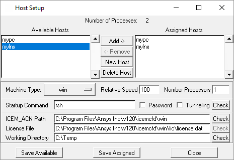
opens the Host Setup panel where you can specify the host settings.

You need to do the following to specify the host settings:
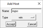
Click to open the Add Host panel where you can define the host machine. Specify the name of the host and select the operating system type from the Type drop-down list. Click .

All defined hosts will be listed in the Available Hosts list. Select the host in the Available Hosts list and verify the relevant parameters.
Number Processors specifies the number of processors on the machine.
The Startup Command allows you to use either the remote shell client (
rsh) or secure shell client (ssh). Enable Password if you require a password to access the machine. You may click the button to verify that the startup command works correctly.Verify that the ICEM_ACN Path and License File path are correct and specify the Working Directory as appropriate.
Click to save the settings for the available hosts.
Select the host in the Available Hosts list and click to add the host to the Assigned Hosts list. To remove a host from the Assigned Hosts list, select the host and click . You can also permanently delete previously defined hosts using the button.
Click to save the settings for the assigned hosts and close the Host Setup panel.
- Number Processes
specifies the number of processes.
- Connect Timeout
specifies a timeout for connecting to the host machine.
- Verbose Print
enables the printing of detailed messages in the message window.


