


 The unstructured
hexahedral smoother relaxes unstructured hexahedral meshes in order
to obtain smooth grid lines orthogonal to the boundary as well as
smooth grid angles and transitions in the inner volume. It first smoothes
the surface mesh recognizing the topological boundary edges. If the
number of volume smoothing steps is greater than 0, after each surface
smoothing step the inner volume will be adjusted by performing 1 volume
smoothing step. After the surface smoothing has been finished, the
inner volume will be smoothed (according to the number of volume steps
set). It can also smooth pure surface meshes.
The unstructured
hexahedral smoother relaxes unstructured hexahedral meshes in order
to obtain smooth grid lines orthogonal to the boundary as well as
smooth grid angles and transitions in the inner volume. It first smoothes
the surface mesh recognizing the topological boundary edges. If the
number of volume smoothing steps is greater than 0, after each surface
smoothing step the inner volume will be adjusted by performing 1 volume
smoothing step. After the surface smoothing has been finished, the
inner volume will be smoothed (according to the number of volume steps
set). It can also smooth pure surface meshes.
The mathematical basis is that an elliptical differential equation
of the form  , where
  is the "control function",
will be solved. It can be proved that by using the elliptical operator
is the "control function",
will be solved. It can be proved that by using the elliptical operator  , smoothness of the mesh will be achieved. The control
function
, smoothness of the mesh will be achieved. The control
function  will be specified so that the smoothed mesh will
obtain certain characteristics, such as orthogonality and layer height
of the first layer.
will be specified so that the smoothed mesh will
obtain certain characteristics, such as orthogonality and layer height
of the first layer.
The unstructured hexahedral smoother is available under (to smooth an existing mesh) and under (to smooth the Hexa pre-mesh). If you select , the pre-mesh will be calculated (if it does not exist), and then you can select the Orthogonality option for the Smooth Method for the unstructured hexahedral smoother.
Note: If you smooth the pre-mesh (Blocking), the smoother may move vertices and change edge distributions undesirably. If you are outputting a structured mesh, you should save the blocking first so you can return to the previous state if necessary. If you are outputting in an unstructured mesh format, you should first convert to unstructured mesh and then use the > option.
Tips to improve smoothing success:
Create the best possible starting condition by matching edge distributions.
Create points (geometry) at the ends of the edges, and then associate the vertices (block) to them. This may be used to contain an area of fine mesh along a wall, preventing it from being totally smoothed out.
The following smoothing parameters are available:
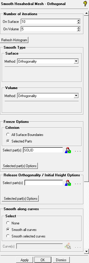
- Number of iterations
- On Surface
specifies the number of iterations the smoother uses to relax the surface mesh. The minimum number of smoothing iterations to be completed for stability reasons is 10. The default number of iterations on surface is also 10.
- On Volume
specifies the number of iterations the smoother uses to additionally relax the volume mesh after surface smoothing has been finished (minimum is 0). When the number specified is greater than 0, a volume smoothing step will be performed after each surface smoothing step to adjust the volume mesh to the surface mesh. The default number of iterations on volume is 5.
- Refresh Histogram
updates the quality measure histogram.
- Smooth type
For both Surface and Volume, the drop-down lists contains the following three options:
Orthogonality
The smoother will try to retain orthogonality and the height of the first layer. For surfaces, orthogonality implies that the first layer grid lines will be orthogonal to the surface edges.
Laplace
The smoother will try to equalize the mesh by setting the control function f to 0 in the elliptical differential equation.
Structured
The smoother offers two additional choices: Sorenson methods attempt to maintain node distributions (bunching) near the surface boundaries while improving orthogonality. It could be one of two types. Hilgenstock methods maintain orthogonality and first layer height, and may be one of two types.
Selecting Structured causes a second drop-down list to appear. The following four options are available:
Sorenson/Laplace: This attempts to improve orthogonality at the boundary while maintaining the first layer height from the boundary surface and making a uniform node distribution in the interior.
Sorenson/Thomas & Middlecoff: This method improves orthogonality at the boundary while maintaining the first layer height from the boundary surface and holding the original clustering on the interior.
Hilgenstock/Laplace: This attempts to improve orthogonality and uniform node distribution within the mesh.
The Hilgenstock/Thomas & Middlecoff method tries to maintain orthogonality at boundaries while holding the first layer height. With Thomas & Middlecoff as the background control function, the original clustering is intended to be maintained.
Note: During smoothing, the volume mesh will be separated into an inner (Volume) part and boundary (Surface) part which will be smoothed independently of each other. The boundary (surface) elements will be smoothed first, then the inner volume will be adjusted to the smoothed surface boundary, and finally the inner (volume) elements will be smoothed. Hence, it is advisable to set the same Smooth type for both Surface and Volume.
- Freeze Options
All Surface Boundaries
freezes all boundary node locations.
Selected Parts
allows you to specify freeze options for selected parts. Select the part(s), then click . Specify the frozen surface boundary by enabling Surface boundary. Specify the number of layers to be frozen with the surface boundary by disabling Surface boundary and entering the number of layers n in the Layers field. The number of layers is set to 0 by default. When Layers is greater than 0, then the surface boundaries including the first n layers from the boundary will be frozen. For example, a value of 3 indicates that three layers of nodes away from the surface will be frozen along with the surface boundary.
(A) Enabling Surface boundary
(B) Specifying number of layers
- Release Orthogonality / Initial Height Options
For certain situations, it may be helpful to release the orthogonality requirement from a certain surface part or set the first layer distance (initial height of the first element off the wall) on certain surfaces. These are mutually exclusive since orthogonality is required to set the first layer height. Select the desired parts, and then click . The default is to release orthogonality for each part. You can set the initial height by disabling Release orthogonality and then set the initial height by entering it in the Initial Height field.
Note: You can set the Initial Height to
-1(default) in order to keep the starting initial height.(A) Enabling Release orthogonality
(B) Specifying Initial Height
- Smooth along curves
allows you to specify which edges (projected onto curves) should be smoothed. The smoothing will be carried out when faces are smoothed. You can specify none, all, or selected curves. The default is all.
Note: If the mesh distribution has a relatively large dynamic range of mesh sizes along a curve, then selecting this option may be counter productive.
- Advanced Options
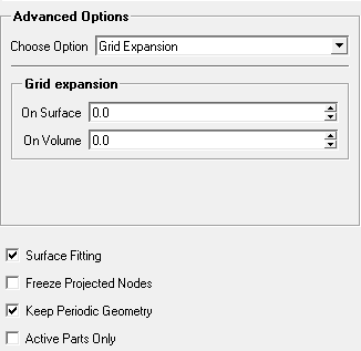
The drop-down list contains the following advanced smoothing options:
- Grid Expansion
If a smoothing method other than Laplace is selected, then the grid expansion values will be used to distribute the control function values into the inner volume. If the grid expansion rate is greater than 0.0, the algorithm computes a pseudo-structured region in which the control function values will be interpolated by an exponential decay (the grid expansion rate will then control the negative exponent (e power -g) of the control function values). If it is 0.0 then a Laplace interpolation of the control function values will be done. That is, for an inner node, the control function value will be averaged by the control function values of its neighbor nodes.
The default values are 0.0 for the surface mesh and for the inner volume. Reasonable values other than 0.0 should be greater than 1.0.
Note: It may be difficult to form the pseudo structured regions in some cases. If you have such problems, set the grid expansion rate back to 0.
Note: If the grid expansion rate is set to 0.0 and the smooth type is set to Orthogonality, the first layer height and the orthogonality at the boundary are still achieved, but the next layers tend towards Laplace approaching the middle of the mesh. In case of a Navier- Stokes mesh you can see the effect near the boundary where the first layer is orthogonal to the boundary but the next layers curve as they equalize (Laplace) the distances of the layer nodes.
- Treat unstruct nodes
determines the method of treating inner unstructured nodes. An unstructured node is a node on which no ij (surface) or ijk (volume) directions can be defined. That is, a node which has more or less than 4 (surface) or 6 (volume) neighbors is clearly an unstructured node.
Figure 432: Initial Mesh shows the mesh before smoothing. The highlighted node is an unstructured node, while all other nodes are structured. Figure 433: Smoothed Mesh shows the mesh after smoothing.
Bisector
Each structured neighbor node will be positioned in a bisector angle with respect to the unstructured node and the two other neighbors. The grid line between the node and the unstructured node will be in a bisector angle to the 2 grid lines between the unstructured node and the corresponding neighbor node from left and right. The distance will be calculated in a heuristic way. If the neighbor node is unstructured then it will be positioned using the Laplace method.
Laplace
Each neighbor node will be positioned using the Laplace method.
Modified Laplace
Each structured neighbor node will be positioned using the Laplace method, but comparing its distance to the unstructured node with the appropriate distances of the unstructured node to its other neighbors (should not be greater than a certain ratio). If the neighbor node is unstructured then it will be positioned using the Laplace method.
The hexahedral smoother works better on structured meshes because it can use structured elliptical smoother methods which are more powerful than the methods for the unstructured parts for which it mainly uses Laplace.
Note: For most models, the effect of the this setting may be negligible.
- Stabilization Factor
is used in the calculation of the new nodes and should be greater or equal to 1.0. A higher factor will make the smoother more stable at the cost of orthogonality at the boundaries. If there are problems with the smoother it is recommended that this value be increased to around 8.0. Default values are 1.0 on surfaces and 2.0 in the volume. Increasing this parameter may be helpful on certain model configurations if the smoother corrupts the mesh, especially if it appears due to overly orthogonal boundaries.
- Use Orthogonal Distance
if enabled, then the original boundary distance of a first layer node will be calculated by projecting it to the boundary and measuring the distance to the projected point. Otherwise, the length of the original grid line will be used. By default this option is disabled for both the surface and volume.
In cases where there is a sharp angle between the grid lines from the first layer to the boundary, if Use Orthogonal Distance has not been set, the calculated first layer distance may be considerably greater than the distance of the first layer nodes to the boundary (because the length of the grid line will be used). Hence, it may be advisable to set Use Orthogonal Distance in the same way for both Surface and Volume. This would ensure that the first layer grid line angles in the volume near the surface boundary would be similar to the nearby surface boundary grid line angles.
- Define Edges on Part Border Options
The border grid lines attached to the selected parts will be defined as edges. The main purpose for defining these edges is that they separate the two sides of the surface mesh. If an edge is topologically internal then orthogonality will not be established there.
- Fix Orientations
If Volume is enabled, then before smoothing takes place, all volume elements will be checked to see if the node order defines a right-handed element and will be fixed if necessary.
Note: Enabling this option could result in additional calculation time.
- Surface Fitting
constrains boundary nodes to the true geometry surfaces. When disabled, the original mesh faces are used to determine the boundary constraints. This option is enabled by default.
- Freeze Projected Nodes
When set, all nodes which are prescribed or projected to the geometry (curves or surfaces) will not be allowed to move.
- Keep Periodic Geometry
when enabled, ensures that the mesh will stay on the geometry on periodic sides. Otherwise the periodic nodes can move away from the geometry. Nevertheless periodicity is still guaranteed. This option is enabled by default.
- Active Parts Only
if enabled, only the active parts (parts that are turned on (activated) in the Parts branch of the display tree, see the Parts section) will be smoothed. The geometry or mesh of the active parts does not need to be displayed. When this option is disabled, the whole mesh will be smoothed. The histogram displayed will also reflect the setting of the Active parts only option. This option is disabled by default.
If you click or the mesh smoothing will be started. If is selected, then the window will be closed afterwards.