- Flood Fill
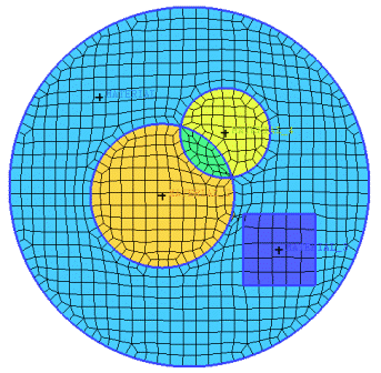
The Flood Fill process here is the same as what happens during the Octree meshing process. Flood Fill uses Material points to mark volume elements and group them into volume parts. See also the Octree meshing approach in the Ansys ICEM CFD User's Manual.
For each material point in the model, a root volume element is defined (the volume element that this material point sits in). From each root volume element, all the neighboring volume elements will be added, and then their neighbors are added in a flood filling manner. This process stops at the surface elements which define the closed boundary and selects all the volume elements within the boundary. The selected volume elements are assigned to the part of the material point within the volume.
Note: If the flood fill process finds a second material point with a different part name within the same process, leakage is detected. Flood fill will attempt to automatically close holes, but if it cannot, the application will prompt you to close holes interactively. A message will alert you to which material point entities are in conflict. In the interactive process, you will be shown a jagged line representing the connection path between the material points along the centroids of the volume elements and through the "hole" if there is one. It will also highlight the single edges and bring up the mesh editing option for mesh from edges so you can more easily select the edges and close the hole. Then the flood fill will resume. In some cases, the problem may be that both material points are in one volume or perhaps one is in the wall between two volumes; in which case deleting or moving material points is the solution.
Note: For situations where the mesh is not surface fitted, use the Mark Enclosed Elements option instead of Flood Fill.
- Make volume mesh consistent with surface mesh
makes tetra volume mesh consistent with tri surface mesh. Tetra elements near the surface are modified to fit the surface mesh. The final volume mesh is connected node for node with the surface mesh. You can use this command to replace a boundary or cut a surface mesh out of a volume.
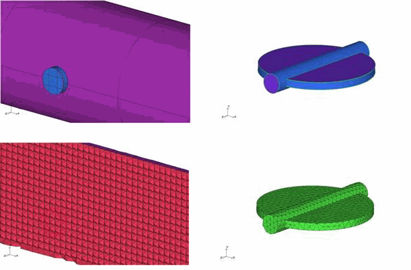
Figure 439: Original Volume and Surface Meshes shows a manifold with an inserted baffle. The tetra volume mesh for the manifold and the tri surface mesh for the baffle is also shown.
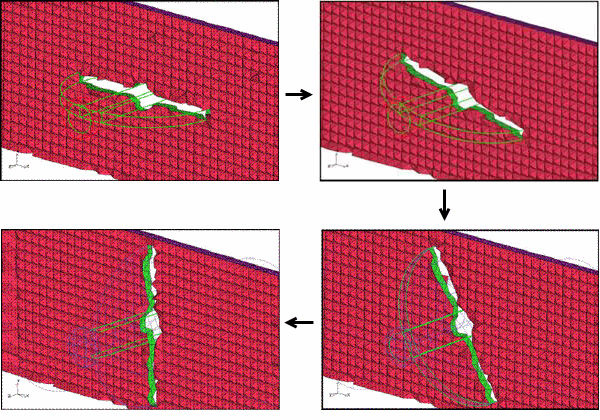
Figure 440: Combined Mesh shows the combined mesh, where the use of this option allows you to combine the two meshes in different orientations.
This option may be chosen for All elements, or Selected elements.
Note: Most manual mesh editing commands, such as merge, split, etc. automatically keep the volume consistent. Other commands, such as remesh from edges have an option to "Keep volume consistent".


