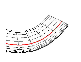
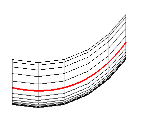
This method allows you to o extrude mesh along a curve which defines variable direction. By default, the orientation of each layer will be perpendicular to the curve.
- Extrude curve
specifies the existing curve along which elements should be extruded.
- Show curve directions
if enabled, an arrow indicating the direction of the selected curve will be displayed.
- Orient axially
The orientation of each extruded layer of elements will be the same as that of the original layer of elements.
Figure 414: Extrusion Orientation
By default, the orientation of the extruded layers will be perpendicular to the curve.

If is enabled, the orientation of the extruded layers will be the same as the original layer of elements.

- Reverse curve direction
allows you to extrude elements in the opposite direction to the curve direction (parametric).
- Project to Geometry
if enabled, then all new boundary nodes will be projected to surfaces. The last layer of new nodes will have the same projection type as the original nodes.
- Number of layers
specifies the number of layers to be extruded. By default it extrudes one layer.
- Twist per layer
specifies the number of degrees for the elements to be rotated per layer. This is used for helical extrusions.
- Spacing type
You can choose a Fixed spacing for each element or Curve bunching, which will use the Spacing and Bunching law parameters that are specified for the Curve Mesh Size.


