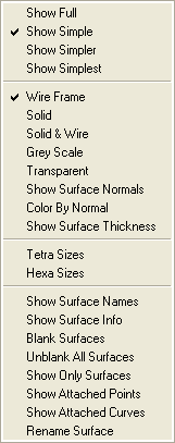
The display options for Surfaces are shown below.
- Show Full
A more detailed representation of the CAD data, showing more isobars than in the Simple representation. For triangulated surface data, a detailed representation will show all the surface triangles.
- Show Simple
A wireframe representation of CAD data or a "Hard Feature" representation of triangulated surface data, including surface boundaries as hard features.
- Show Simpler
This wireframe representation requires less memory than the Simple option. This option is beneficial for simplifying more complicated models, and making them easier to translate or rotate.
- Show Simplest
This representation uses the least memory. This option is recommended for simplifying models that are extremely complicated.
- Wire Frame
The surfaces are drawn using lines, in either simple or detailed formats.
- Solid
A solid or shaded representation of the surface data, which can be either simple or detailed.
- Solid & Wire
A combination of the Solid and Wireframe representations of the surface data.
- Grey Scale
This will convert the color geometry into grey scale.
- Transparent
This will show the surface as transparent.
- Show Surface Normals
When enabled, arrows indicating the positive normal direction of each visible surface will be displayed.
- Color by Normal
When enabled, the part color is used to indicate the positive normal side of each visible surface. The reverse side of each surface is colored gray.
Note: This option works only with Solid or Solid & Wire display.
- Show Surface Thickness
This will show the thickness assigned for the surface.
- Tetra Sizes
Selecting this option will display the reference tetra mesh sizes upon the selected visible surfaces.
- Hexa Sizes
Selecting this option will display reference hexa sizes upon the selected visible surfaces.
- Show Surface Names
Displays the names of the visible surfaces.
- Show Surface Info
Gives information about a selected surface, including the surface and part names.
To employ this option, select . Proceed to select a surface with the left mouse button and accept the selection with the middle mouse button. Information on the surface or surfaces will be listed in the Messages window.
- Blank Surfaces
Blanks the selected surfaces.
- Unblank All Surfaces
Restores blanked surfaces.
- Show Only Surfaces
Displays the selected surfaces only.
- Show Attached Points
Displays points that are attached to the selected surface.
- Show Attached Curves
Displays curves that are attached to the selected surface.
- Rename Surface
To rename the selected surfaces.


