The options allow you to change the display settings for Ansys ICEM CFD using the options in the Settings-Display DEZ. Some changes in settings will be effective only after restarting Ansys ICEM CFD.
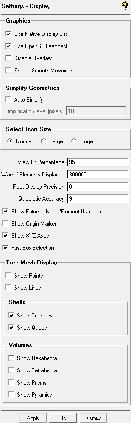
- Use Native Display List
enables the use of OpenGL or another accelerated graphics library when possible. The final color including the lighting effects are fixed until the surfaces are refreshed. This option is recommended, because the color and lighting effects are updated for every redraw. Depending on the system and machine, this option may result in slower display redraws. Some nVidia graphics cards may show slower performance when this option is enabled.
Note: If you encounter graphics performance problems, disable the Use Native Display List option and click . You do not need to restart Ansys ICEM CFD for this change to take effect.
- Use OpenGL Feedback
enables the use of OpenGL's feedback mechanism to detect the 3D coordinates of the location on the model that the mouse is pointing to. This option is recommended when the option Use Native Display List is enabled, since it allows the program to release the memory holding the model's geometry data once it has been used to create the display list.
- Disable Overlays
disables the use of overlays in drawing a selection box since some graphical cards perform slower with this option.
- Enable Smooth Movement
Enable Smooth Movement improves display performance, allowing you to rotate very large models smoothly. With this option enabled, you will need to double-click to change the model’s center of rotation, in Dynamic Mode. See The Ansys ICEM CFD GUI in the User’s Manual and Mouse Bindings/Spaceball in the Help manual.
- Simplify Geometries
contains options for simplifying the geometry rendering.
- Auto Simplify
simplifies geometry rendering as the model is zoomed out. This option can speed up rendering of large assemblies or models containing a large number of surfaces. The Simplification level (pixels) option sets the threshold for simplification.
- Simplification level (pixels)
sets the threshold for simplifying geometry rendering. As the model is zoomed out, surfaces of less than the specified number of pixels across are displayed in a more simplified way in order to speed up graphics performance. The default is 10 pixels, meaning that as the model is zoomed out and each surface becomes less than 10 pixels across, its display is simplified.
Figure 59: Simplifying Geometry Rendering shows a jet with surfaces shown as Wireframe with Show Full enabled, and Simplification level set to
50pixels. As the model is zoomed out, the smaller surfaces fall below the 50 pixel threshold, and the display is simplified.
- Select Icon Size
specifies the icon size. You can select Normal, Large, or Huge, as required. The software must be restarted before any change will take effect. If your screen resolution is very high, you may prefer the Huge setting.
ICON SIZES Tab DEZ (Data Entry Zone) Normal 24 35 Large 35 35 Huge 35 48 The font size will also change depending on the icon size set and the screen resolution.
- View Fit Percentage
determines the percentage of the screen on which the model will be displayed when the Fit to Screen option is used. For example, if set to 90, when Fit to Screen is selected, the model will displayed on 90 percent of the total height and width of the screen display. The default of 95% is usually sufficient to prevent the on-screen prompts from obscuring a portion of the model.
- Warn if Elements Displayed
sets the threshold number of elements that will be displayed without a warning. These elements are displayed according to the Tree Mesh Display settings after the mesh is loaded. The default value is 1000000, and the value 0 will disable the warning completely.
In the case of Tetra Octree mesh, this warning is displayed before the in-process smoothing. If the specified number is exceeded, a popup window will tell you the number of elements about to be displayed and ask if you want them to be displayed.
Note: If you are generating large numbers of shell elements and do not want to display them, disable them under Tree Mesh Display.
- Float Display Precision
sets the number of decimal places displayed.
- Quadratic Accuracy
makes the Bspline display a smoother curve.
- Show External Node/Element Numbers
displays the external Node or Element information. Internally, these numbers may be different in order to optimize the meshing routines, but most users prefer to interact with the external numbers as they were before being imported into Ansys ICEM CFD or as they will appear after export. This affects the behavior of node and element number display, as well as features such as creating a subset from node numbers.
- Show Origin Marker
displays the origin marker on the screen.
- Show XYZ Axes
displays the XYZ axes in the bottom right corner. This triad is interactive and clicking on it will orient the display.
- Fast Box Selection
enables the "-overlay" option for the selection box. This can increase performance when there are millions of selected items. Since the memory or accuracy penalty is small, it is recommended that it is enabled for all models.
- Tree Mesh Display
allows you to select the default elements which are displayed when a geometry or mesh is loaded. You can enable the display of points, lines, shell elements (triangles and quads), and volume elements (hexahedra, tetrahedra, prisms, and pyramids) as required. On a large model, displaying all the Shells by default may take too long, so you may want to disable the shell elements. When computing a large tetra mesh, disabling Show Triangles would prevent the time consuming display of these elements before and during the in-process smoothing steps.