The following 3D block types can be created:
- Mapped
allows you to create 3D mapped (structured) blocks by specifying the vertices, edges or faces of adjacent blocks.
Select a Method and specify the blocking features (faces, edges or vertices) by clicking or by manual entry.
- Corners
Select eight vertices (or locations) as shown in Figure 314: Selection of Vertices/Locations for Mapped Block Creation to create 3D mapped blocks.
While selecting a combination of vertices and locations:
First select the vertices to be used, ensuring that the order of selection is appropriate.
Click the middle-mouse button to confirm the selection of the vertices.
Select the remaining locations on the geometry (not necessarily points) to complete the selection of 8 vertices/locations.
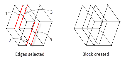
- Edges
Select four edges to create a new 3D mapped block. Order of selection is important (Z-pattern) to avoid block errors.
- Faces
Select faces of adjacent blocks as shown in Figure 316: Selection of Faces for Mapped Block Creation to create a new 3D mapped block.
Note: The selected faces must be mapped. Other types will generate a warning message.
- Swept
allows you to create a swept block by selecting corners, edges or faces of adjacent blocks.
Select a Method and specify the blocking features (faces, edges or vertices) by clicking or by manual entry.
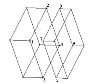
- Corners
Select six or more vertices in order (different than for mapped block creation). In the example shown, eight vertices are selected as endpoints of four edges in a U-pattern.
- Edges
Select three or more edges, in order (different than for mapped block creation). In the example shown, four edges are selected in a U-pattern to form the edges of a swept block.
- Faces
Select two faces to create a 3D swept block.
Note: This operation converts mapped blocks to swept blocks. If there is a swept or free block included in the blocks that are to be converted, there may be an error.
- Quarter Ogrid
allows you to create the advanced topology known as a Y-Block or Quarter Ogrid. This topology is used to fit three Hexa Blocks into a wedge. Select six vertices/locations as shown in Figure 319: Selection of Vertices/Locations for Quarter Ogrid to create the Quarter Ogrid. The three vertices of one side of the wedge must be selected first, in clockwise or counter clockwise order. Then the remaining three vertices can be selected. It is important that the 4th vertex selected should be connected to the 1st, 5th to the 2nd and 6th to the 3rd respectively.
While selecting a combination of vertices and locations:
First select the vertices to be used, ensuring that the order of selection is appropriate.
Click the middle-mouse button to confirm the selection of the vertices.
Select the remaining locations on the geometry (not necessarily points) to complete the selection of 6 vertices/locations.
- Degenerate
allows you to create a degenerate block which is a prismatic block with 5 sides. Previously, these could only be created by collapsing one side of a hexa block to create a wedge. The bottom up creation follows the exact same method as the Quarter Ogrid (Y-Block) creation. However, only one block is created and there will be a row of prism elements along one edge. Many solvers can not handle this type of blocking, so be sure to consult your solver manual before using degenerate blocks.
Select six vertices/locations as shown in Figure 321: Selection of Vertices/Locations for Degenerate Block to create the Degenerate block. The 4th vertex selected should correlate to the 1st, the 5th to the 2nd, and the 6th to the 3rd.
While selecting a combination of vertices and locations:
First select the vertices to be used, ensuring that the order of selection is appropriate.
Click the middle-mouse button to confirm the selection of the vertices.
Select the remaining locations on the geometry (not necessarily points) to complete the selection of 6 vertices/locations.
- Sheet
allows you to create a structured sheet block from 4 vertices. The vertices should be selected in the order of a Z pattern (shown in Figure 323: Selecting Vertices/Locations for a Sheet Block). Click the middle mouse button to confirm the selection of the vertices.
- Free-Sheet
allows you to create a free sheet block from 4 vertices.