


For body-fitted sector-mesh cases, a periodicity boundary will be present and should be associated with the two vertical faces of the sector. The sector periodicity information will be determined automatically and is displayed in the Editor panel for reference.
General requirements for the body-fitted sector geometry include:
The piston is assumed to be at its BDC (bottom dead center) position in the surface mesh.
The sector/cylinder axis must be aligned precisely with the z-axis.
The front periodic surface should be precisely in the X-Y plane.
Requirements 2 and 3 are automatically satisfied in a mesh generated by Ansys Forte's Sector Mesh Generator.
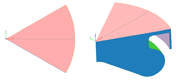
For AMG (Automatic Mesh Generation) sector-mesh cases, a periodicity boundary condition should be added and associated with the two vertical faces of the sector. For sector geometries other than 90° or 180°, the sector angle is automatically calculated based on the surface geometry. General requirements for the AMG sector geometry include:
The piston is assumed to be at its TDC (top dead center) position in the surface mesh.
The sector/cylinder periodic axis must be aligned precisely with the z-axis.
The sector must be symmetric about the positive X-Z plane, that is, the central plane of the sector must be aligned with the X-Z plane as in Figure 3.21: Sector alignment for periodicity.
90° and 180° Periodicity
Due to the nature of Forte's underlying Cartesian mesh, there are two special cases that can exploit the Cartesian alignment for 90° or 180° sectors. These special cases require a different alignment.
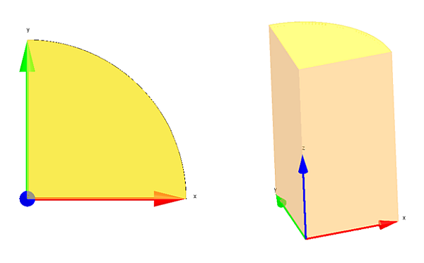
For 90°sector geometry, the geometry should be aligned so that the periodic surfaces occupy the X-Z and Y-Z planes, as shown in Figure 3.22: Sector alignment for periodicity.
For 180° sector geometry, the geometry should be aligned so that the periodic surface is aligned with the X-Z plane and is centered about the Y-Z plane, as shown in Figure 3.23: Sector alignment for periodicity.
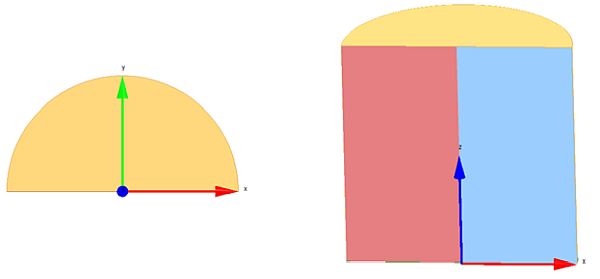
Projects making use of Forte’s automatic meshing capability (AMG) can also define a symmetry boundary condition. The geometry should be aligned so that the symmetry plane is aligned with the X-Z plane and is centered about the Y-Z plane. This is similar to the 180° alignment shown in Figure 3.23: Sector alignment for periodicity.