


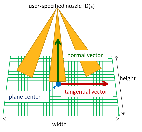
A spray patternator is used to track how much liquid mass from certain nozzles has crossed a monitor plane and where the liquid crosses the monitor plane. For each spray patternator, you can choose which nozzle(s) to monitor (Injection Source) and specify the location, orientation, size, and resolution of the monitor plane. The monitor plane is a discretized two-dimensional rectangular plane. The following parameters are needed to define the plane (see Figure 3.34: Schematic drawing of spray patternator configuration):
Plane Origin: The center of the rectangular plane.
Plane Normal Direction: The normal vector of the plane.
Plane Tangential Direction: The tangential vector is used to define the "width" direction of the rectangular plane. Since this tangential vector is parallel to the plane (or within the plane), it must be orthogonal to the normal vector of the plane. If their mutual orthogonality is not satisfied, the Forte run will report this error and stop.
Width and Height of the plane: By convention, the width direction is aligned with the tangential vector.
Number of grid points along the Width and Height directions: Used to specify the resolution of the discretized 2-D plane.
Spray patternation results can typically be saved at a lower output frequency compared to other types of monitor probes, so Forte allows a customized output timing control to be specified for each patternator. If the Custom Output Timing box is checked, the output schedule of this patternator will follow the custom timing instead of the top-level monitor probe output timing.
The Activation options are used to control when a spray patternator becomes active. The patternator will stop accumulating the spray parcels crossing the monitor plane when becoming inactive.
The patternator output files will be saved in a sub-directory called spray_patternator under the Run directory. Results are reported in Ansys EnSight gold casefile format. At each result-writing step, one set of output files is created for each patternator, including a .case file, a .geo file, and N+1 .var* files, where N is the number of nozzles monitored in this patternator. The base-name of these output files follows the same convention as the one used by .ftres files. An example is T_1.00E-03_100_Patt_1.case, in which 1.00E-3 is time and 100 is time step. The .case file serves as an index file, which contains references to the .geo and .var* files. The first N .var* files contain the areal mass densities (g/cm2) of accumulated liquid mass crossing each 2D cell from each individual monitored nozzle, and the last .var* file contains the total areal mass densities (g/cm2) from all monitored nozzles.
To visualize the patternation results in EnSight, open the .case file in EnSight, and a part called Patternator Plane will be created. By default, the Patternator Plane is shown as a point field. To change the view to a plane, right-click the Patternator Plane part, select Edit, and on the Editor panel, change the Mesh option under Creation from Original dataset mesh to Height surface, projecting points onto XY plane. Then you can render the plane using the areal mass density variables.
If needed, you can overlay additional .case files or the .ftind file in the same EnSight viewport. To do so, choose Keep current loaded data when you open the additional .case or .ftind files.