


For turbulent premixed or partially premixed flames in SI engines, the heat release due to turbulent flame-front propagation constitutes a major portion of the total in-cylinder heat release. For this reason, we refer to this as the "primary heat release."
The Ansys Forte G-equation model assumes a flame
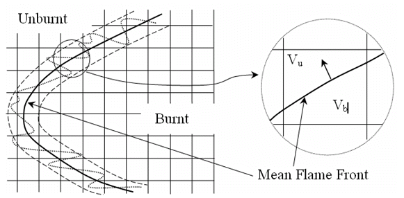
structure shown schematically in Figure 7.3: Numerical description of the turbulent flame structure
. For the heat-release calculation,
the Ansys Forte model builds on this assumption using the method described by Liang et al. [52]
. This method uses the sub-grid scale
unburned/burned volumes of the flame-containing cells and assumes that the mean flame-front
surface cuts every flame-containing cell into two parts, an unburned volume  and a burned volume
  , as shown in Figure 7.3: Numerical description of the turbulent flame structure
. As the mean flame front sweeps
forward, the mixture within the sweeping volume tends to move towards a local instantaneous
thermodynamic equilibrium, following a constant pressure, constant enthalpy process. Under some
conditions that result in low flame temperatures, such as high equivalence ratios or high
exhaust gas residuals, the mixture within the sweeping volume might not fully reach equilibrium.
Ansys Forte provides two options for the chemistry in the flame front-region: an Equilibrium
treatment, or a stirred-reactor reactor model operating with a residence time that is
representative of the flame thickness (patent pending) [72]. In theory, if infinite residence time were
available, results with the stirred reactor model would approach those of the equilibrium model.
The stirred-reactor model allows for non-equilibrium chemistry in the flame front that is to be
expected under some operating conditions. The pressure is assumed to be homogeneous across the
flame within the cell, consistent with deflagration wave theory. The sub-grid scale volumes are
tracked for every time step based on the coordinate information of the cell vertices and the
flame surface piercing points.
, as shown in Figure 7.3: Numerical description of the turbulent flame structure
. As the mean flame front sweeps
forward, the mixture within the sweeping volume tends to move towards a local instantaneous
thermodynamic equilibrium, following a constant pressure, constant enthalpy process. Under some
conditions that result in low flame temperatures, such as high equivalence ratios or high
exhaust gas residuals, the mixture within the sweeping volume might not fully reach equilibrium.
Ansys Forte provides two options for the chemistry in the flame front-region: an Equilibrium
treatment, or a stirred-reactor reactor model operating with a residence time that is
representative of the flame thickness (patent pending) [72]. In theory, if infinite residence time were
available, results with the stirred reactor model would approach those of the equilibrium model.
The stirred-reactor model allows for non-equilibrium chemistry in the flame front that is to be
expected under some operating conditions. The pressure is assumed to be homogeneous across the
flame within the cell, consistent with deflagration wave theory. The sub-grid scale volumes are
tracked for every time step based on the coordinate information of the cell vertices and the
flame surface piercing points.
If the Equilibrium option is
chosen, the species conversion rate and the associated primary heat release rate are calculated
by first determining the equilibrium concentration and adiabatic flame temperature under
constant pressure and constant-enthalpy constraints. If the stirred-reactor model is chosen, the
species conversion rate and the associated primary heat release rate are calculated using the
residence time within the flame. Then for a flame-containing cell, we assume the mean flame
front sweeps throughout the unburned volume  within time step dt. Taking into account the portion of
the mixture within the swept volume that reacts, the species conversion rate of species
k for time step dt reads
within time step dt. Taking into account the portion of
the mixture within the swept volume that reacts, the species conversion rate of species
k for time step dt reads
 | (7–33) |
where ρ and  are cell-averaged densities of the total mixture and species
k and where the swept volume is approximated by
are cell-averaged densities of the total mixture and species
k and where the swept volume is approximated by
 | (7–34) |
where  is the mean flame-front area within the cell, and
  the turbulent flame speed.
Finally the conversion rate of species k can be written as
 | (7–35) |
Numerical integration of Equation 7–35
using an explicit Euler method
gives the updated species density  .
.