


This section describes the numerical method to solve the volume fraction transport equation (Equation 11–17).
In the CICSAM model proposed by Ubbink [99], the
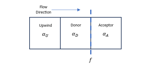
convective flux across a cell face is computed by evaluating the volume fractions on both sides
of the face. Consider the cell face denoted by  in Figure 11.1: Definitions of the donor, acceptor and upwind cells used by the CICSAM model, depending on the local flow
direction, the two neighboring cells adjacent to are denoted as “donor” and “acceptor”,
respectively, so that the flow leaves the donor and enters the acceptor. The cell further
upstream of the donor cell is denoted as the “upwind” cell.
in Figure 11.1: Definitions of the donor, acceptor and upwind cells used by the CICSAM model, depending on the local flow
direction, the two neighboring cells adjacent to are denoted as “donor” and “acceptor”,
respectively, so that the flow leaves the donor and enters the acceptor. The cell further
upstream of the donor cell is denoted as the “upwind” cell.
Volume fraction is a scalar stored at the cell centers. A normalized volume fraction,
 , is defined as follows:
 | (11–21) |
In the CICSAM model, the Normalized Vector Diagram is applied to design a numerical scheme that is not artificially diffusive or produces unphysical oscillations. The model uses a Hyper-C scheme [47] that has the “compressive” feature, which helps sustain the sharpness of an interface:
 | (11–22) |
In which  is the normalized volume fraction at face , and the subscript
  refers to the Convective Boundness Criterion used by the Hyper-C scheme.
 is the normalized volume fraction of the donor cell and
  is the Courant number.
While the compressive scheme is good at maintaining the sharpness of the interface when it is perpendicular to the flow direction, it results in artificial “wrinkles” to the interface parallel to the flow direction. To remedy this, the CICSAM model considers ULTIMATE-QUICKEST (UQ) scheme:
 | (11–23) |
As a result, the normalized volume fraction at face is computed as:
 | (11–24) |
In which  is a blending factor accounting for the interface’s orientation with
respect to the flow direction:
is a blending factor accounting for the interface’s orientation with
respect to the flow direction:
 | (11–25) |
 | (11–26) |
where  is a parameter taken as 1,
  is the included angle between the interface’s direction and the flow
direction. The interface’s direction is taken as that of the volume fraction’s
gradient in the donor cell,
is the included angle between the interface’s direction and the flow
direction. The interface’s direction is taken as that of the volume fraction’s
gradient in the donor cell,  . The flow direction is defined by the vector connecting the cell centers of
the donor and acceptor,
. The flow direction is defined by the vector connecting the cell centers of
the donor and acceptor,  .
.
Using Equation 11–24
and Equation 11–21, volume fraction at face
is computed, and it is used to compute the convective fluxes of both liquid
and gas volumes at the face. The volume fraction transport equation (Equation 11–17) is solved explicitly to obtain the volume
fraction in each cell after convection.
Since the CICSAM model is formulated for one dimension, an explicit split operator approach is used to extend the method to three dimensions. Specifically, the model is first applied to compute the convection of liquid volume fraction in one dimension. Then, the liquid volume fraction values in each cell are updated. Subsequently, we apply the model to compute the convection of liquid volume fraction in another direction. The procedure continues, until convections in all three dimensions are computed. The order of directional split is altered randomly in each time step [80].