


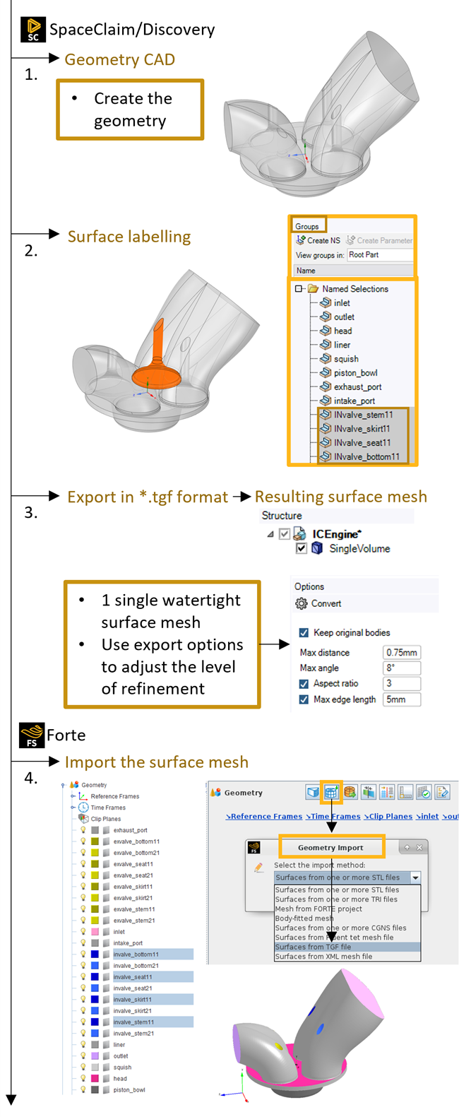
Forte allows the volume mesh to be generated on the fly and cut down the preprocessing time. Only the surface mesh is needed to setup the simulation, and this can be easily generated and imported in Forte in 4 simple steps as it is shown in Figure 3.1: Generate the surface mesh in 4 steps:
Create your CAD geometry. Ansys Discovery is the preferred geometry tool.
Group and label the surfaces. It will be easier later in Forte to set up the boundary conditions and add fixed surface depth mesh refinements. In Ansys Discovery, look for the option Group > Create NS (named surface). Alternatively, this step can be performed in Forte once the surface mesh is imported.
Export the geometry in *.tgf format. This automatically creates the surface mesh needed by Forte. Pay attention to the following during this step:
Make sure the geometry is watertight. The fluid domain must be one and one only and must be fully connected.
The export options define the quality of the surface mesh. Setting the options too small might cause the final surface mesh to be too big in size and slow down the actual simulation. However, setting them too coarse could cause features loss and accuracy degradation of the results. As a general guideline, the total surface mesh in the *.tgf format should be around 10 to 15 MB. For an optimal compromise, use the following export options when saving the surface mesh in *.tgf format:
Max distance: 0.75 mm
Max angle: 8°
Aspect ratio: 3
Max edge length: 5 mm
If multiple components are present, like in a gerotor or in a compressor geometry, make sure they don't intersect each other and that all the solid volumes are embedded in the fluid domain.
Import the surface mesh in Forte from the Geometry tree and select the *.tgf format.
A pop-up message will ask you to choose the import units. Make sure what you select is consistent with the units used in the CAD generation.
If you forget to specify the correct units, once the surface mesh import is done, simply select all the surfaces in the Geometry tree, right-click, select Transform and specify the correct scaling factor for the X, Y, and Z direction.
Units are completely configurable in Forte. Units can be modified inline in the input panels, or by going to Edit > Preferences > Units Preferences. You can choose from CGS, SI, British, or create your own Custom unit preferences.
Applications That Require Special Attention
Forte's range of applications is quite large, so before starting your simulation, refer to the following list to see if your case requires special treatment before importing the geometry.
For geometry involving rotors, it is better to create a small clearance between the end surfaces of the rotors and the casing so that they won't overlap with each other. A distance of 0.5 or 1 micron is typically sufficient.
When dealing with round surfaces that are very close to each other, increasing the surface mesh resolution is helpful in avoiding surface intersections. Compressor simulations are a typical example.
In System Coupling simulations like Conjugate Heat Transfer (CHT) or Fluid Structure Interaction (FSI) simulations, sufficient surface mesh resolution is strongly suggested on the coupling interfaces. These simulations need to interpolate volume mesh results to the surface mesh nodes to perform coupled physics calculations. In System Coupling simulations, the surface mesh resolution on the coupling interface should be comparable between the different software participants.
Similarly to System Coupling analyses, Forte's built-in FSI simulations are also required to have a sufficient surface mesh resolution to provide realistic and locally accurate results.