The following are some of the common causes for meshing errors.
Incorrect surface normal directions. In compressor cases, after a geometry is imported, either the rotors or the casing needs to have their surface normal vectors inverted. When a geometry is replaced, this inverting step must be repeated on the new geometry.
Material point going out of the domain. Make sure the material point is not in the way of a moving valve or a rotor. In engines with canted valves, such an error is difficult to detect during the setup stage, so it is safer to put the material point near the spark plug or near a spray injector.
Surface intersection. This can be caused by a lack of tolerance between two walls, coarse facets in the geometry file, misplaced rotors, or incorrect rotation axis specifications. It is always a good idea to use the Preview Simulation utility to check for surface intersections during the setup stage.
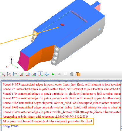
Surface mesh is not watertight. This is caused when either the surface mesh presents unwanted holes or when neighbor surfaces are not properly connected. A red error message is printed out in the console within the Forte UI, and the holes or the disconnected edges are highlighted in red in the graphic window. The error message looks like Figure 3.2: Example of a non-watertight surface mesh error.
Additionally, troubleshooting instructions for the following common issues are covered in this section:
- 3.2.1. Error Caused by Surface Intersection (Assertion Failure)
- 3.2.2. Mesh Generation or Mesh Preview Takes a Very Long Time
- 3.2.3. Diagnosing Error: Vertex Reached Unexpected Location
- 3.2.4. Orphan Cells When Using the Automatic Mesh Generator
- 3.2.5. Error Converting Mass Flow Rate Into Velocity for Boundary
If there is a surface intersection present, you may encounter an "Assertion failed in cut cell creation" error during the Forte simulation. The error message usually looks like Figure 3.3: Typical error message for "Assertion failed in cut cell creation" error.
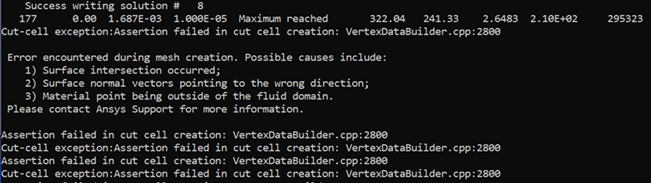
Alternatively, you may also encounter an "Unexpected error in mesh generation" error.
Along with these error messages, certain .stl files would have been written to the working directory. The output .stl files are only produced when there is a surface intersection.
To diagnose, first look for any diagnostic .stl files in the working directory after the failure. You can import them into the Forte project along with the project's original geometry to identify where the assertion failure occurs. Check the locations of the intersecting pieces.
However, usually this does not give you detailed information regarding how the surfaces intersect, especially in a moving-boundary simulation where the failure occurs after the simulation has run for a while. To get more information, you may also want to run Mesh Generation in Preview Simulation in the original Forte project, with Check for Surface Intersections turned on. Generate the mesh preview around the exact time when this error occurs, to see if any surface intersection is reproducible or not.
After the mesh generation is completed, open the mesh preview results in Ansys EnSight by clicking Launch Ensight on the Mesh Generation panel. If any surface intersection is reproduced, you will see a group of "intersection" points marked by the crosses, as seen in Figure 3.5: Surface intersections as seen in EnSight.
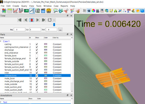
Note that not all the intersection marks are necessarily problematic. You can just focus on the marks that correspond to the assertion failure's location (as seen from those .stl files).
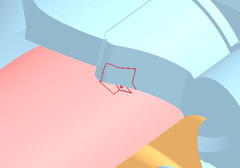
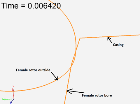
Making some cut planes at those locations can typically show you how the surfaces intersect locally. Note that what is loaded into EnSight are the surfaces defined in the geometry. The interaction between a cut plane and the surfaces resulted in curves. Ideally, different curves should not intersect with each other. Shown in Figure 3.6: Surface intersections viewed using cut planes, you can see that the curve representing the "Female rotor outside" surface is intersecting with that of "Female rotor bore", meaning that these two surfaces have intersected. This tells us the root cause of the problem.
Most likely, the error is due to surface intersection, and you should look into
the surface mesh geometry. If you still cannot identify the source of the problem,
set AMG_DIAG = 1 and share the logs with Ansys
Support.
Try launching the Mesh Preview with the default parameters without including the volume mesh nor the surface intersections options.
Sometimes, the problem is due to excessive mesh refinement. See the screenshot shown in Figure 3.7: Typical error message for excessive mesh refinement for the error reported by the console.
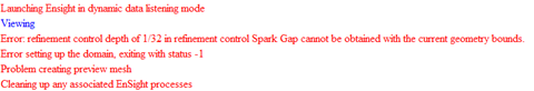
Note: There is a limit in Forte to the depth of refinement achievable given the bounds of a particular geometry. In general, you can take the largest edge of the box bounding the geometry (if there is a stroke, consider it to be fully extended) and divide it by 16384 to get a limit on the smallest mesh size allowed.
If the issue persists, try the following to diagnose the problem:
Try running the simulation with different numbers of cores (more, or less) or on a different platform and see if the same problem persists.
Try running the simulation with the same settings at a different time. Sometimes there might be system or hardware issues that prevent your case from running normally.
Have a reliable estimate of the resulting size of the volume mesh, and make sure that the mesh refinement level is not too deep. (Refer to Note)
Try Mesh Preview with the Include Volume Mesh option to see if it also takes a very long time.
Sometimes, due to coding errors, the program could run into "MPI deadlock errors". The current timeout limit of MPI communication is 360 minutes, or 6 hours. So, if mesh generation stalls more than 6 hours, it is unlikely to be caused by MPI deadlock. (However, the operation to stop the run when heartbeat limit is reached is not guaranteed to work all the time. If the system or the network is simply too busy or overloaded or there is issue with the MPI connectivity, MPI_Kill may not work.)
If none of the above helps, add the following environment variable to the run:
AMG_DIAG = 1This will force the mesh generation program to output extensive debug info. Share the output with the development team for further assistance.
The error message caused by this error usually looks like Figure 3.8: Typical error message for "… reached unexpected location z in bcmombal for vertex …" error.
Figure 3.8: Typical error message for "… reached unexpected location z in bcmombal for vertex …" error
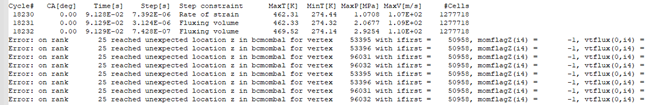
The cause for this type of error is hard to identify, as there might be something wrong with the geometry, settings, or meshing. As a first step, see if you can reproduce it.
Generally, the MONITOR reports even before the crash, a few recycling due to temperature iterations or fluxing. These recycling cycles indicate a rough solution path. These problems are mainly caused by insufficient refinement for the valves. The valve gaps should be refined to 1/4 level (0.5 mm), and be always active to make sure the intake/exhaust port regions and the cylinder region are properly separated when the valves are closed. Without these refinements, the solution fields in these two regions may affect each other through the closed valve. Also, make sure the maximum time step is of the order of 5E-6 s during the combustion phase.
In some Forte simulations using the Automatic Mesh Generator (AMG), you may see a message in MONITOR like this:
"total number of orphan cells across all ranks: 1"
Orphan cells are fluid cells that do not share any cell face with another fluid cell on the partition, hence why they are called "orphan" cells. AMG cannot guarantee to not have orphan cells on a partition. Once they show up, they can cause trouble since there is no connection between the orphan cells and the other fluid cells on the partition. But the issue should go away by itself when the new AMG mesh does not include any orphan cells.
Orphan cells cannot be removed once they are generated during mesh update, and there is also no special treatment for them on the Forte solver side. While it is not guaranteed, AMG will try its best to not generate orphan cells.
You may want to run the case with "-v debug" option to
make sure nothing abnormal is going on in mesh generation. This option will perform
some expensive mesh integrity checks during mesh movement and property
mapping.
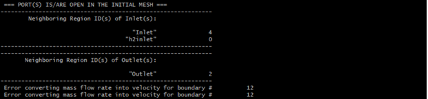
A possible cause for this error is that the mesh resolution at this inlet/outlet is too low and there is no cell face defined as open boundary face. Take a look at the mesh there and see whether the inlet/outlet surface is sufficiently resolved.
Look at the region ID neighboring each inlet/outlet as seen in Figure 3.9: Console output displaying region IDs of the inlets/outlets. In the following case, the region ID neighboring h2inlet is 0. This indicates that there is no cell face that has a boundary condition ID matching the boundary condition ID of this h2inlet. Such symptoms can be caused by either low mesh resolution or a region ID error in meshing