


This section provides step-by-step how-to instructions on the following topics:
For a screw compressor simulation, if refining the facets in the geometry file does not help or is not practical, shrinking the rotors' sizes and compensating that using the gap size scale factor may be the best approach. There is no golden rule, but you can take a look at the current smallest gap size (on average), especially between the rotors and the casing, and aim for doubling this size. You can measure the current rotor diameter D and the current smallest gap size Sgap. If you want to double the gap size, the shrinking factor for the rotor diameter is Sgap*2/D. Of course, the gap sizes between the rotors will be increased by a value larger than Sgap, but it is difficult to adjust the gap sizes proportionally everywhere. After this adjustment, you can apply 0.5 as the scale factor.
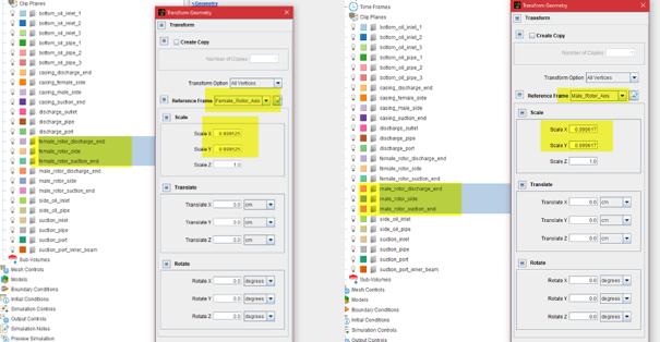
Note that both the male and female rotors need be adjusted. The shrinking should be applied to their proper reference frames.
For geometry involving rotors, it is better to create a small clearance between the end surfaces of the rotors and the casing so that they won't overlap with each other. A distance of 0.5 or 1 micron is typically sufficient.
To ensure that Forte does not mesh this gap, for each of the rotor (male and female) wall boundary conditions, define its movement type as Sliding Interface. Then, in Select Stationary and Sliding Surfaces, include the four relevant end surfaces for each rotor, which are the two end surfaces of the rotor and two end surfaces of the casing.
To avoid artificial flow penetrating through a thin plate, Forte requires the
surface refinement cell size surrounding the thin plate to be smaller than half of
the plate thickness. If the plate is very thin, the refinement level required might
be very deep. To allow relatively larger cells to be used, you can artificially
increase the thickness of the plate in the geometry and adjust the Young's modulus
accordingly. According to Equation 4–1 to Equation 4–3 in the Ansys Forte User's Guide, the deflection equation is a
function of the term  , in which
  is the Young's modulus and
  is the area moment of inertia of the bending plate. For a
rectangular cross section of the plate,
is the area moment of inertia of the bending plate. For a
rectangular cross section of the plate,  , where
  is the width of the plate and
  is the height of the plate. If is multiplied by a factor of
  in the geometry, to maintain the same value, the should be multiplied by a factor of
  . For example, if the thickness is doubled in the geometry, the
Young's modulus input value should be reduced to
. For example, if the thickness is doubled in the geometry, the
Young's modulus input value should be reduced to  .
.
Backflow happens when pressure specified at the outlet boundary is higher than the pressure in the interior cells. This can indeed happen due to pressure wave propagation in the simulation domain. What is important is that after the outflow rate stabilizes and oscillates around a constant value, that constant value should indicate an outflow (negative, flowing out of the boundary). Momentary backflow is commonly seen in applications like compressors and pumps, especially before the solution reaches quasi-steady state.
That said, it is difficult to eliminate backflow when pressure is specified at an outflow boundary. The fact that the boundary is set as an outlet does not determine the flow direction. Physics (flow inertia, pressure gradients, etc.) determine the flow direction. It is expected that if the simulation settings are correct, the averaged flow direction should be outwards at the "outlet". In simulations of compressors and pumps, this depends on several factors, such as whether the rotors' rotations are correct, and whether the amounts of leakage through the small gaps are predicted correctly.
Surface proximity is an empirical parameter, and it is mainly used to identify fluid cells that are in the gap region ("gap cells"). Knowledge of the gap cells allows Forte to apply the gap flow model to them. Another usage of surface proximity is to apply the user-specified mesh refinement to the gap cells after they are identified.
Despite what its name might suggest, surface proximity is not the same as the actual geometric spacing in the gap. The general guideline for picking a surface proximity value is:
Surface proximity should be set to be equal to or slightly larger than the local volume mesh size near the surfaces that form the gap, after considering the surface depth mesh refinement applied to the surfaces and before considering the gap feature mesh refinement.
Therefore, surface proximity is more related to the local volume mesh size, which is typically much larger than the actual geometric gap.
For example, if the surface refinement in the gap region gives 0.5 mm cells, the surface proximity can be set to 1.5*0.5 mm = 0.75 mm. Such a setting can help make sure that the identified gap region is large enough to avoid any void in the volume mesh.
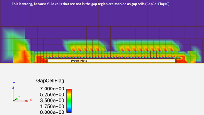
If the surface proximity is set too large, Forte could wrongfully mark cells that are not in the gap as "gap cells". This could cause solution to become problematic and unstable.
Conversely, if the surface proximity value is too small, then the pocket tracking results in a compressor simulation could be unexpected. Pocket tracking relies on the gap region to isolate the volumes between different chambers.
A good sanity check is to open the spatially-resolved solution in EnSight and color a cut plane or surface of interest by "GapCellFlag". Zero means non-gap cells, and positive integers mean gap cells. Figure 5.41: Result of wrong surface proximity settings is the result of the wrong settings:
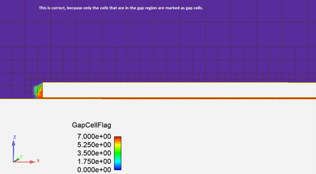
After setting the proper surface proximity for each of the gap feature mesh controls, the gap cells should be correctly marked in each gap region. Figure 5.42: Result of correct surface proximity settings shows the results.
If you want to reduce the volume marked as gap region, you should consider using deeper surface refinement in this region and then reduce the surface proximity value accordingly.