


This type of FSI component can be used to model a flexible reed valve which undergoes
cantilever deformation. The beam deflection dynamics equation is approximated by using
an analogy to rigid body torsional rotation. The deflection angle  is solved by integrating the following equation over time:

where  is the net torque applied on the beam with respect to the anchoring
axis,
is the net torque applied on the beam with respect to the anchoring
axis,  is the restorative torque caused by the beam's stiffness,
 is the torque from external pressure applied on the beam surface,
 is a damping coefficient, and
  is the mass moment of inertia of the beam.
This equation is integrated in time explicitly:

In the actual bending beam, the deflection angle varies at different locations along
the beam. In the present model, the deflection angle is defined as an averaged quantity.
The change of  is related to the change of the tip deflection
  through the following equation:

The restorative torque is correlated with the deflection distance of the tip of the beam based on the statics analysis using Euler's beam equations. This correlation is derived for three different load models: point load, distributed load, and partially distributed load.
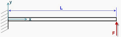
In the point load model, the static deflection distribution along the beam is given by:
 | (4–1) |
where  is the point force,
  is Young's modulus,
  is the area moment of inertia of the beam,
  is the distance from the deflecting point being calculated to the
anchoring end of the beam.
is the distance from the deflecting point being calculated to the
anchoring end of the beam.
The restorative torque is correlated with the tip deflection through the following equation:

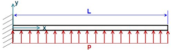
In the distributed load model, the static deflection at location  along the beam is given by
 | (4–2) |
where  is external force per unit length.
The restorative torque is correlated with the beam tip deflection through the following equation:

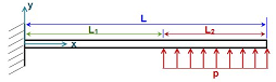
In the partially-distributed load model, the static deflection at the location
 along the beam is given by:
 | (4–3) |
where:

The restorative torque is correlated with the beam tip deflection through the following equation:

A displacement threshold may be specified to control when the FSI part would start to move. The FSI part would not move geometrically until the tracked displacement would exceed the displacement threshold. A maximum displacement may also be specified, and an option may be set to limit the deflection motion to travel in only the positive direction with respect to the specified beam axis.
From the physical properties of the valve material, the Young's modulus must be provided to specify the stiffness of the solid material.