Use the Blank tab to define the blank of the forming process. For more information on adding blanks to the forming simulation, see Defining the Blank (Blank Tab).
In addition to the Common Ribbon Elements, the Blank ribbon contains tools that enable you to define the material blanks that will be operated on during the process. Selecting the Blank ribbon automatically displays the most recently selected Design-n Task Panel.

- Add
Choose this command to create a new design for a material blank. This will create a new Design-n button on the ribbon.
- Design-n
The Blank Ribbon Elements contains one button for each blank design that has been defined in the project. These are numbered. Click a button to load that blank's design parameters into a Design-n Task Panel where they can be viewed and modified.
Choose any button to load that blank's design
parameters into this task panel where they can be viewed and modified. Create new
blank components by clicking the
button ( ). Modify
components in the table by clicking cells. You can toggle a preview of the blank's
location, choose a label color for the blank, set the blank component, choose a
material, set the blank component rolling angle, and set the blank component
thickness. Remove a blank component from the list by clicking the delete button
(
 ) at the end of
that component's row in the table.
To define symmetry in the blank, check the Blank Symmetry check box, then click the button to open the Blank Symmetry Task Panel.
Click the button ( ) at the top of the Design-n Task Panel to view and modify parameters for this
Blank design. Change a property value and click Enter to activate
the button. When you are finished, click the
button.
To set the blank component of this Design, select the third column of a component's row to open this panel. Choose Pick Options to choose options that control how you select objects in the geometry for modification.
Click the button in the Outlines section to create a new Blank outline, or select an existing outline from the list and click the button to modify that outline. Either action will open the Blank design: Outline Task Panel.
Click the button in the Holes section to create a new hole in the Blank, or select an existing hole from the list and click the button to modify that hole. Either action will open the Blank design: Hole Task Panel.
When you are finished defining or modifying the Blank, click to save your changes, then click to return to the Design-n Task Panel.
Use the tools in this task panel to draw shapes and define coordinates that define the Outline of the Blank. When you are finished, click to return to the Define Blank by Curve Task Panel to save your changes, or click to discard your changes before returning.
Use the tools in this task panel to draw shapes and define coordinates that define pre-existing holes in the Blank. When you are finished, click to return to the Define Blank by Curve Task Panel to save your changes, or click to discard your changes before returning.
The following features enable you to choose the material used to create the project blank, modify the properties of a material, and save material definitions to a reusable library.
To assign the material of this Design in a Design-n Task Panel, select the fourth column of a component's row to open this panel. You can import a material definition, export the current definition to a file, or define a new material in the Material Editor/Viewer by clicking buttons in the task panel's toolbar.
To assign a material that has already been defined within or copied to the project, select a material from the list of Project Materials, then click to save your assignment and return to the Design-n Task Panel.
To assign a material from a library, select a material from the AnsysForming Library, then click to view that material's properties in the Material Editor/Viewer. If the material's properties conform to your needs, click (you may need to check Agree to continue before this button becomes active).
To copy a material to the project without assigning it at this time, choose from the drop-down menu that is attached to the button (again, you may need to check Agree to continue before this button becomes active).
Click to return without copying or assigning the material.
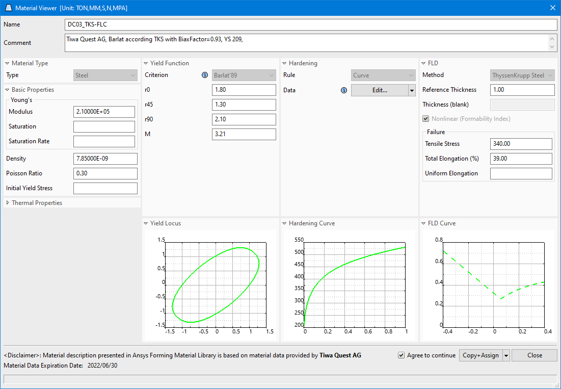
The Material Editor and Material Viewer are windows that enable you to review or modify material properties and save those library materials or custom materials to the project.
Note: You must define the FLD properties of the material here if you wish to create a Forming Limit Diagram during postprocessing. See Viewing a Forming Limit Diagram for more information about the FLD.
You cannot make changes to the material definitions in the Material Library. First, you must copy the material definition to the project using the Material Viewer. Once you have copied the material definition to the project, you can open the copy in the Material Editor.
To make changes to a material definition that has been copied into the project, select a material in the Project Materials list and click Open or double-click a material in the Project Materials, edit the values in the properties fields of the Material Editor, then click . The Yield Locus, Hardening Curve, and FLD Curve plots are updated based on the changes you make to the associated properties.
To assign an edited material, click . To save the edited material to the project without assigning it at this time, choose from the drop-down menu that is attached to the button.
If you have exported several modified materials, or received material keyword files from other sources, you may wish to place them in a local User Materials Library to make it easier to copy those material definitions into projects.
To Create a User Materials Library:
Create a library directory on your local computer and give it a logical name.
Place all materials files in that library directory.
On the (
 ) menu, choose +System.
Scroll down to > and select .
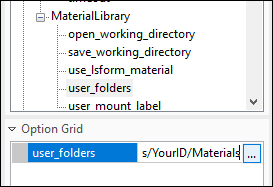
In the Option Grid, double-click the field next to user_folders.
Enter a full directory path (including the drive letter) to the library directory.

Select .
In the Option Grid, double-click the field next to user_mount_label.
Enter a text name that will be used in the Material Library Task Panel to label your materials library.
Click .
Click .
You will need to exit and re-launch Ansys Forming before your user materials library is visible in the Material Library. Once it is available, you can select, copy, and assign materials from this library just as you would from the AnsysForming Library.
To define symmetry in the blank, open this task panel from the Design-n Task Panel by checking the Blank Symmetry check box and clicking the button.
Use this task panel to select symmetry settings such as whether the input geometry defines the whole blank or half of the blank, the planes of symmetry, and the local coordinate system. Click to save your changes to the Blank then click to return to the Design-n Task Panel, or click to return without saving.


