To improve Aerodynamic Damping analysis (also known as blade flutter analysis), you can perform one-way coupling of Ansys Fluent with Ansys Mechanical. The CFD solver requires input from FEM in the form of mode-shapes. The mode-shapes are imposed on the blade to prescribe its vibration.
These mode-shapes are provided in *.CSV files generated by
Ansys Mechanical (FEM solver) and are read into Ansys Fluent with the following data for aero-damping
applications:
Parameters with units
Spatial fields with units
Data field names with units
Face-Node connectivity
Parameters
The parameters section of the
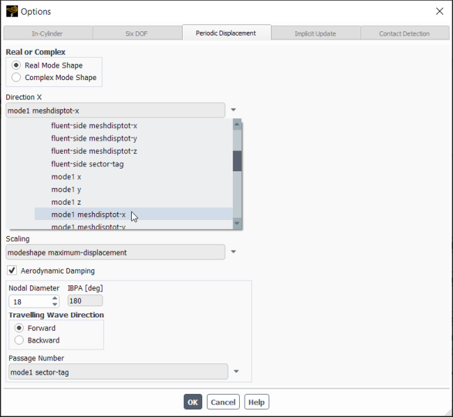
*.CSVfile is typically a parametric name followed by a parametric value. Fluent reads this section of the file as a single value profile variable (for example, frequency = 1024.4 [Hz]). This single value profile variable allows you to select it in periodic displacement settings, as shown in XREFTO IMAGE, typically this is followed by the profile name and its corresponding parametric name.
Spatial Fields
This section describes the generic names for coordinates (for example, Initial X [m], Initial Y [m], and so on).
Data Field Names
This section uses the spatial field coordinates followed by the other field names (for example, meshdispotot-x, meshdispotot-y, and so on). Each data field name has corresponding profile values at each coordinate point. The data field name is used as a profile variable that you may select and display.
Face-Node Connectivity
This section includes the connectivity for the nodes of each facet in the mesh. This is use to correctly display the cells described by the profile in Fluent.
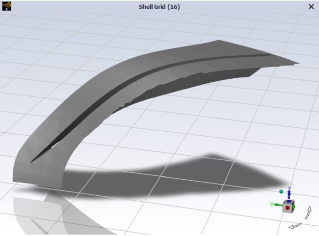
The following is an example of the expected formatting of a CSV profile that you can use to describe mode shapes for enhanced aerodynamic damping analysis.
# EXPROFILE,SURF,MODE,0,normmodeshape,mode1nd4norm_connectivity,csv, ,
[Name],,,,,,,,
normmodeshape,,,,,,,,
,,,,,,,,
[Parameters],,,,,,,,
Ncompt = 3,,,,,,,,
Nnodes = 4404,,,,,,,,
Harmonic Index = 4,,,,,,,,
Mass = 7.2581159 [kg],,,,,,,,
Frequency = 1422.6964 [Hz],,,,,,,,
Maximum Displacement = 2.4339259 [m],,,,,,,,
,,,,,,,,
[Spatial Fields],,,,,,,,
Initial X [m], Initial Y [m], Initial Z [m],,,,,,
,,,,,,,,
[Data],,,,,,,,
Initial X [m], Initial Y [m], Initial Z [m], norm meshdisptot x [ ], norm meshdisptot y [ ], norm meshdisptot z [ ], norm imag meshdisptot x [ ], norm imag meshdisptot y [ ], norm imag meshdisptot z [ ]
0.26249194,-0.15531575,-2.57E-02,-0.26383738,-0.27941432,-0.10469795,0.24519758,-1.56E-02,0.88077954
0.26336359,-0.15383309,-2.57E-02,-0.26204233,-0.28049517,-0.12765918,0.23875593,-1.19E-02,0.88023709
0.26452365,-0.15182963,-2.57E-02,-0.25952255,-0.28202344,-0.15844249,0.22989663,-6.86E-03,0.87890624
0.26538526,-0.15031855,-2.57E-02,-0.25755007,-0.28318918,-0.18149755,0.22306774,-2.95E-03,0.87750092
<note - many lines removed>

,,,,,,,,
[Faces],,,,,,,,
175,3045,3016,2790,,,,,
2790,3016,3001,2789,,,,,
2789,3001,2986,2788,,,,,
2788,2986,2971,2787,,,,,
<note - many lines removed>
With beta features enabled (as described in Introduction), you can read and use mode-shapes.
Reading the profile and using it:
Open the Profiles dialog box by clicking in the Physics ribbon tab (Zones group box).
 Physics → Zones
→ Profiles...
Physics → Zones
→ Profiles...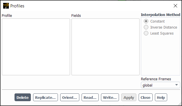
Click and select the profile(s) you want to use.
Display the profile to visualize the defined cells by selecting Profile (and optionally a Field to color by) and clicking Display.
Assign the mode shape definitions for the periodic displacement.
Enable Periodic Displacement in the Dynamic Mesh task page (Options group box).
 Setup → Dynamic
Mesh
Setup → Dynamic
MeshClick in the Options group box to open the Options dialog box and select the Periodic Displacement tab. If Periodic Displacement is the only enabled option, the Periodic Displacement tab will automatically be selected when you open the dialog box.
Select the Real Mode Shape option under Real or Complex to use the settings in the CSV file.
Click the drop-down arrow to select the appropriate profile variable for each field, as shown in Figure 22.4: Selecting a Profile Variable.
Click to confirm the settings updates.