


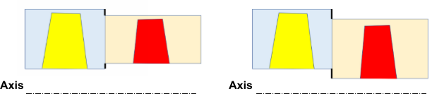
In many turbomachines, the hub or the shroud walls from one blade row to another may not be at the same radial height (axial machine) or axial position (in radial machines). This topological discrepancy results in what sometimes is termed a lip feature. The lip feature can be an actual flow blockage such as walls or can be bleed or injection.
To access this feature, enable beta feature access (Introduction).
To model this feature (if it exists in the geometry) you must select the Non-Overlapping Wall option when creating a General Turbo Interface (GTI). For a Pitch-Scale or No Pitch-Scale interface, this is all that is needed to model a frozen rotor or Transient Rotor/Stator case with the lip feature.
The non-overlapping part of the interface forms walls by default. These walls are listed with wall boundary conditions. If the lip feature happens to represent a region of injection or bleed then you can change the boundary to an inflow or outflow boundary.