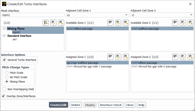
With beta features enabled (as described in Introduction) the Create/Edit Turbo Interfaces dialog box includes an Overlay Zone/Interfaces check box to enable/disable this dynamic highlighting feature. Once enabled, the complete grid outline is shown in gray wireframe in the graphics window. Note the Display button is disabled if the Overlay Zone/Interfaces option is selected.
Figure 22.1: Create/Edit Turbo Interfaces Dialog Box with Overlay Zone/Interfaces Enabled shows the selected cell zones, mesh interface, and
available zones. If both the selected Adjacent Cell Zone-1 and
Adjacent Cell Zone-2 are not set to all then
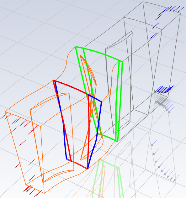
the selected cell zone faces are highlighted in orange (as shown in Figure 22.2: Graphics Window with Overlay Zone/Interfaces Enabled). The selected Available Zone-1 and
Available Zone-2 are shown in red and blue, respectively. The selected
mesh interface shows Assigned Zone-1 and Assigned
Zone-2 in green, indicating the zones are paired.
The dynamic highlighting feature highlights the selected cell zone faces, mesh interfaces, and available zones in the existing graphics window. If a particular zone is not drawn in the graphics window, the highlight feature will not be able to highlight the selected zone. In this case, the graphics must be reset to the complete grid outline, which can be done by toggling Overlay Zone/Interfaces on/off.