You have the option of using anisotropic mesh adaption, which applies an unstructured adaption that is based on edge operations, and uses the Hessian of one or several variables. This adaption is particularly well suited for simulations with shocks, as it can stretch and refine the cells along the principal directions of the anisotropic features.
Note the following limitations with this adaption method:
It is for 3D meshes only.
It is only applied to tetrahedral cells and in some cases prismatic cells (wedges, pyramids, and hexahedrals). Meshes consisting entirely of hexahedrals cannot be adapted by this method.
Surface adaption is available by default for planar boundary zones only (for example, symmetry planes); to apply it to non-planar boundary zone you must ensure it is of type wall and then pair the zone with an auxiliary geometry definition as part of a geometry-based adaption zone.
The mesh cannot contain boundary zones of type interface.
This adaption cannot be undone (as is possible with PUMA, for example), so it can be important to preserve a copy of the original mesh in case you need to revert.
The mesh cannot contain multiple cell zones.
To apply anisotropic adaption, perform the following steps:
Read a 3D mesh or case file.
Set up the simulation, and generate data by initializing or running the calculation.
Enable access to the beta features (Introduction).
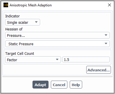
Open the Anisotropic Mesh Adaption dialog box.
 Domain → Adapt
→ Anisotropic Adaption...
Domain → Adapt
→ Anisotropic Adaption... Make a selection from the Indicator drop-down list to indicate whether you want to use the Hessian of a Single scalar or Multiple scalars, and then select the scalar(s) from the Hessian of list.
Make a selection from the Target Cell Count drop-down list, to specify how you want to input the desired change in the number of cells as a result of the adaption. You can select Factor and then enter a multiplier of the current cell count, or you can select Number and enter a value for the desired cell count.
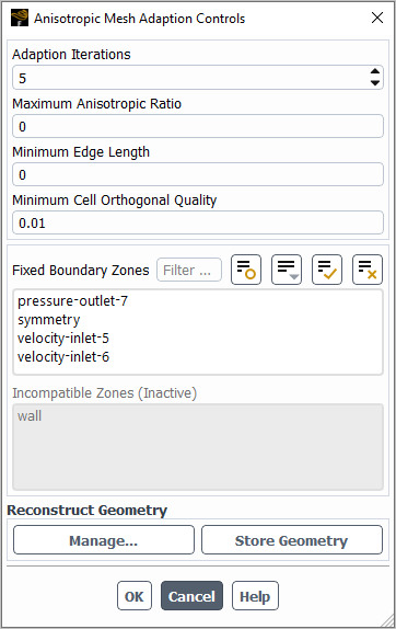
(Optional) You can set advanced controls by clicking the button and using the Anisotropic Mesh Adaption Controls dialog box that opens.
Adjust the number of Adaption Iterations, to control how many sweeps of the operations will be done to update the mesh.
You can specify the Maximum Anisotropic Ratio to set an upper limit to the size ratio of the anisotropic cells created during anisotropic adaption. This size ratio is the largest dimension of the cell as evaluated by the adaption sizing algorithm divided by the smallest. The default value of zero places no limits on the size ratio of cells produced through anisotropic adaption.
You can specify the Minimum Edge Length. This field restricts the size of the cells that Fluent targets for anisotropic adaption. Note that cells with an edge length slightly below this minimum may on occasion be targeted. The default value of zero places no limits on the size of cells that undergo anisotropic adaption.
You can specify the Minimum Cell Orthogonal Quality that you would like Fluent to attempt to maintain in the cells that result from anisotropic adaption. Note that this value is not guaranteed to be maintained, as to do so would negatively affect the solution speed. The worse quality cells will have an orthogonal quality closer to 0 and better quality cells will have an orthogonal quality closer to 1. For more information about cell quality, see Mesh Quality in the Fluent User's Guide.
Make selections from the Fixed Boundary Zones list to specify any zones on which you do not want the anisotropic adaption applied.
Review the zones that are listed under Incompatible Zones. These zones cannot undergo anisotropic adaption. By default, these zones are non-planar (though you can make a non-planar wall zone available for anisotropic adaption through the button, as described in a step that follows). The Incompatible Zones list may affect your selections from the Fixed Boundary Zones list; for example, you may want to treat all boundary zones of type wall in the same way.
If you have a non-planar boundary zone that you want to be available for anisotropic adaption, you must ensure it is of type wall and then pair the zone with an auxiliary geometry definition as part of a geometry-based adaption zone. To pair it, perform the following steps:
Define an auxiliary geometry definition for the shape to which you want the wall to conform, as described in Managing Auxiliary Geometry Definitions in the Fluent User's Guide. Note that you can define the auxiliary geometry definition to be based on the shape of an existing boundary zone by using the Reconstruction type.
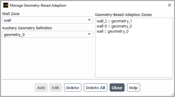
Click the button in the Reconstruct Geometry group box of the Anisotropic Mesh Adaption Controls dialog box, in order to open the Manage Geometry-Based Adaption dialog box.
In the Manage Geometry-Based Adaption dialog box, select a non-planar Wall Zone and the Auxiliary Geometry Definition to which you want the zone to conform, and click the button (note that you must ensure that the existing nodes on the wall zone already conform to this auxiliary geometry definition). The pair will be listed in the Geometry-Based Adaption Zones list. At any point you can select that Wall Zone again and select a different Auxiliary Geometry Definition and click to edit the definition, or you can select it in the Geometry-Based Adaption Zones list and click to delete it. You can repeat this step with different zones to add additional definitions; note that a zone cannot be paired with more than one geometry definition, but a geometry definition can be paired with multiple zones. Click when your geometry-based adaption is fully set up.
The non-planar boundary zone will now be listed in the Fixed Boundary Zones list.
Click the in the Reconstruct Geometry group box of the Anisotropic Mesh Adaption Controls dialog box if all of the following conditions are met:
You paired a non-planar wall with an auxiliary geometry definition using the Manage Geometry-Based Adaption dialog box, and that auxiliary geometry definition is of the Reconstruction type.
You plan to apply multiple cycles of adaption.
Clicking saves an initial copy of the boundary mesh with the case file. This makes the reconstruction consistent between the multiple adaptation applications.
Click to save and close the Anisotropic Mesh Adaption Controls dialog box.
If all of the anisotropic adaption settings are suitable, click the button in the Anisotropic Mesh Adaption dialog box to apply the adaption.
Note: Using the Anisotropic Mesh Adaption dialog box corresponds to the text commands available in the
mesh/anisotropic-adaptionmenu. This menu provides additional functionality:If you need greater control over the adaption process, you can selectively disable the
coarsen?,refine?, and/orswap?operations by using the text commands in the following menu:mesh/anisotropic-adaption/operations/.If you need to smooth jumps in size from the other discrete operations, you can try enabling the following text command:
mesh/anisotropic-adaption/operations/move?.
Run further calculations, and repeat the previous steps to apply further rounds of anisotropic adaption as needed.