


You can review and update the properties of any defined regions using the Update Region Settings task. Any automatically detected regions will be filled with hexcore cells, designated as fluid, and given a single layer of prism cells for the boundary layer.
The Main Region field indicates the name of the primary fluid region for your simulation.
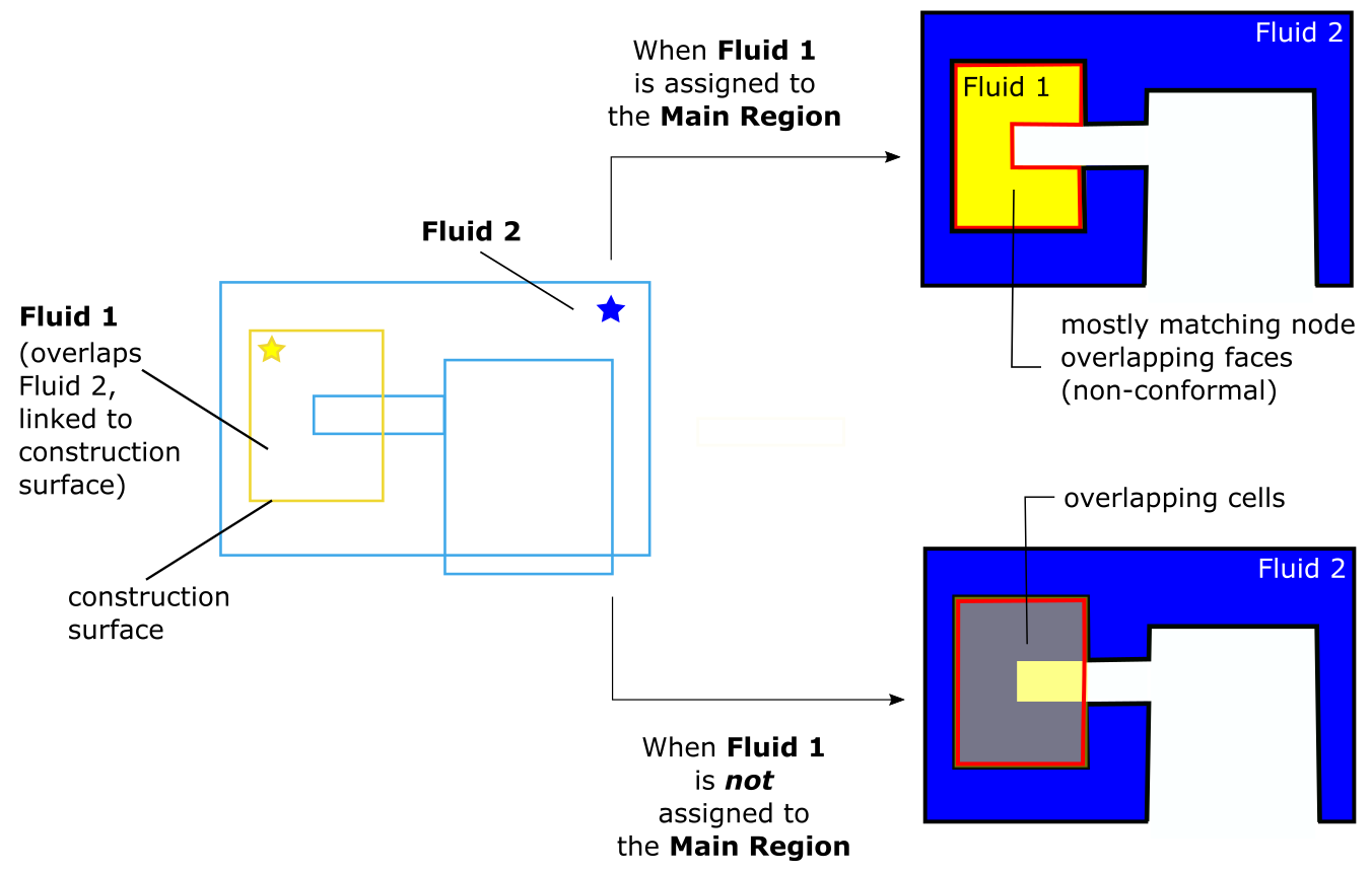
In cases where there are multiple regions to consider, ensure that you choose the correct fluid region, especially in cases where there are construction surfaces, since construction surfaces are only linked to the main region.
Use the Displayed Regions field to indicate how your regions will be displayed in the table. You can select All Regions, Object Based Regions, or Identified Regions. This can be helpful when you have a large number of regions.
(optional) Use the Filter button to filter the table contents based on a particular column.
For regions that are going to be a part of an overset mesh, set the corresponding Overset Component assignment to yes, where you are then restricted to either fluid or void as the region Type.These overset components will be meshed independently.
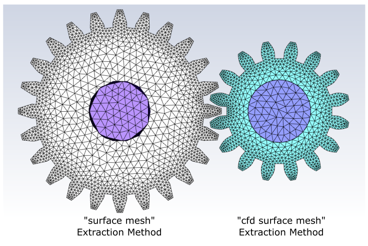
Assign the Extraction Method to either wrap, surface mesh, or cfd surface mesh, for standard and overset regions. In addition, for regions that are going to be a part of an overset mesh, you can also use an existing mesh.
Multiple regions can be assigned a specific extraction method all at once by selecting them in the table, right-click, and select Set Extraction Method in the context menu, then designate an extraction method for the selected regions directly in the menu.
Fluid regions that are within or adjacent to construction surfaces (using the Link to Construction Surface(s) field) will automatically use the surface mesh extraction method.
Note:The cfd surface mesh option allows you to mesh the selected part(s) based on the original CAD model, rather than by using the initial faceting, providing a higher quality surface mesh. Using this option also negates the need to perform any refaceting operations on the imported CAD model in the Import CAD and Part Management task.
To use this feature with SpaceClaim files (
.scdocand.scdocx) or SCDM files, you must use the Workbench option for the Import Route in the Import CAD and Part Management task.If the Extraction Method is set to either surface mesh or cfd surface mesh, there should be no intersection with other regions in the same object.
If the Extraction Method is set to cfd surface mesh for a mesh object that contains multiple volumetric regions, after volume meshing:
All cell zone names will be based on the name of the corresponding region.
If the Type is set to fluid for the meshing object, only volumetric region names containing "fluid" in the name will retain fluid for their type and the rest will be set to solid.
A volume meshing summary will be printed in the console for the meshing object.
Choose a region Type as either fluid, solid, or void.
Multiple regions can be assigned a specific type all at once by selecting them in the table, right-click, and select Set Type in the context menu, then designate a type for the selected regions directly in the menu.
Choose a Volume Fill, or keep the default setting. For both fluids and solids, you can choose from tet, hexcore, poly, or poly-hexcore.
Multiple regions can be assigned a specific volume fill type all at once by selecting them in the table, right-click, and select Set Volume Fill in the context menu, then designate a volume fill type for the selected regions directly in the menu.
Specify a value for the Leakage Size, or keep the default value.
Multiple regions can be assigned a specific leakage size value all at once by selecting them in the table, right-click, and select Set Leakage Size in the context menu, then specify a value for the selected regions directly in the menu.
You can enter values for the Leakage Size directly in the table (for fluid, solid, and void regions that employ the wrap extraction method) rather than by using the Define Leakage Threshold task.
When you are satisfied with the region assignments, click Update Region.
If you need to make adjustments to any of your settings in this task, click Revert and Edit, make your changes and click Update, or click Cancel to cancel your changes.
One or more regions can be visualized all at once by selecting them in the table, right-click, and select Draw Selections in the context menu.
Once all regions have been updated, proceed to the next step in the workflow.