


The Generate the Surface Mesh task will close all the leakages to objects and void regions and then generate only the surface mesh.
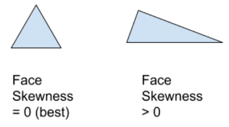
If required, specify the Surface Mesh Target Skewness, or keep the default setting. This value is the target maximum surface mesh quality, and is recommended to be between 0.7 and 0.85.
Select Save Mesh if you would like to save the surface mesh with your simulation. Additional related options are available under Advanced Options.
For Advanced Options, you can:
Indicate whether or not you want to save intermediate files. Select Yes if you want to save files after each major operation such as computing size field, wrapping, surface remesh, etc. This is useful when meshing large models so that you can load those files of interest during the meshing process. Specify the Directory as needed.
Use the Separate Contact Pairs? prompt to indicate whether or not you want to separate contact pairs between fluids and solids in the surface mesh. Contact pairs will be separated during volume meshing and are given the prefix "
i-*" as in, for example,i-1-fs-flureg1:brakepad-brake_pad.1:flu-reg-1,i-2-fs-flureg1:brakepad-brake_pad.2:flu-reg-1, and so on.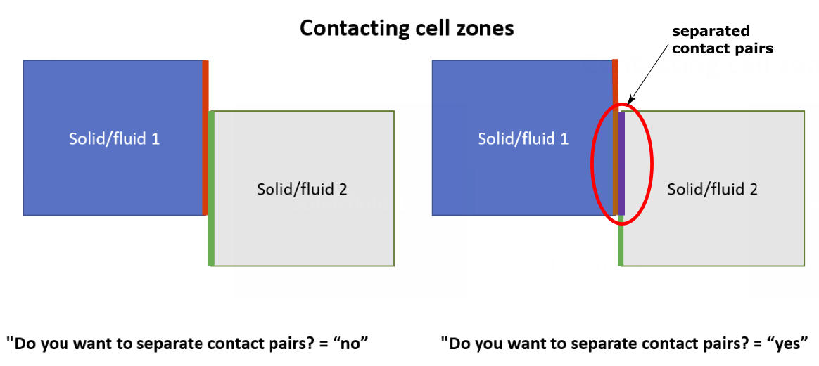
Specify a value for the Maximum Number of Island Faces. Any islands that have a face count smaller than this value will be removed, and only larger islands will remain upon creation of the surface mesh.
Use the Merge Wrapper at Solid Contacts prompt to indicate whether or not you want to allow contacts between solid and fluid regions to be merged into the surface mesh wrapper. When enabled, all bounding faces of a fluid region wrap that come into contact with solid regions will be merged into a single zone (using the prefix
"_contact"). Each respective wrapped fluid region will have one"_contact"zone associated with it.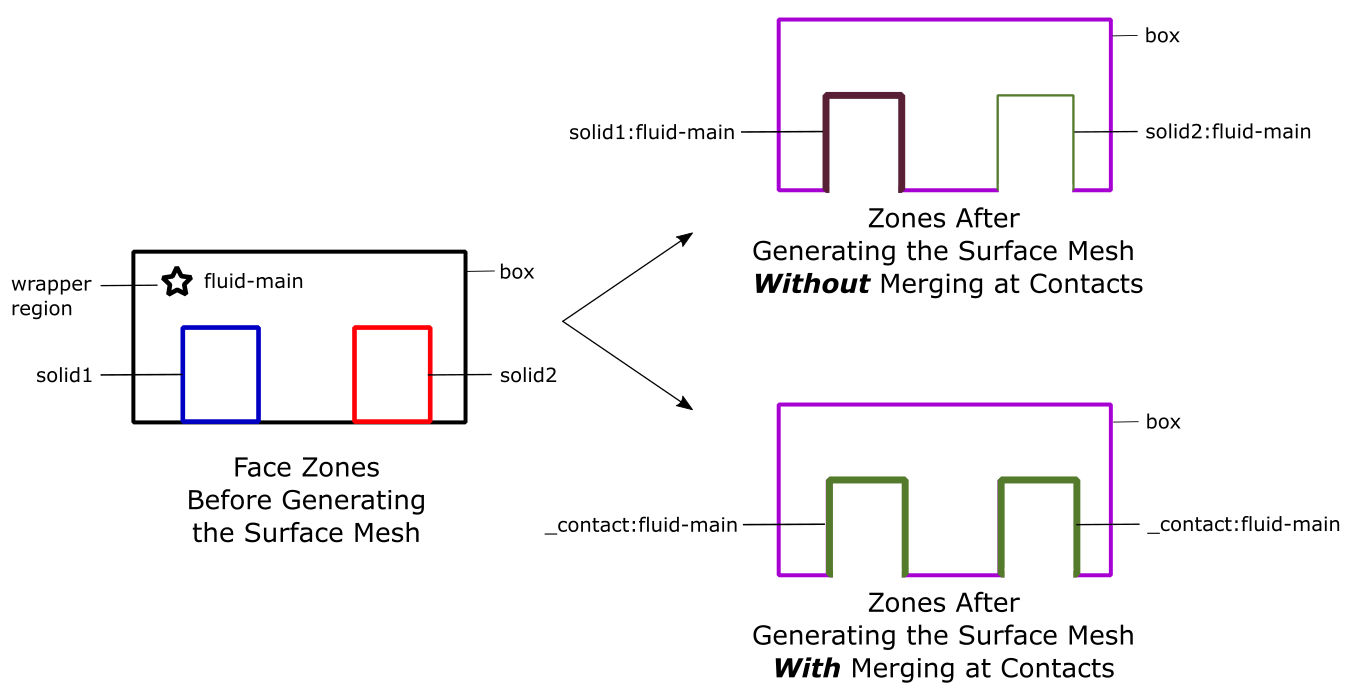
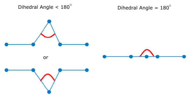
Use the default values, or specify your own values for the Min Spike Angle and the Min Dihedral Angle. These correspond to the minimum spike and dihedral angles of the surface mesh before generating the cells. Additional improvements will be applied to the surfaces based on these quality measures.
Dihedral angles are angles around an edge, such that, for a flat surface, the dihedral angle is 180 degrees, as illustrated below:
The spike angle is the sum of the angles around a node, such that, for a planar surface, the spike angle is 360 degrees, as illustrated below:
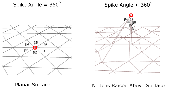
Note: When generating the surface mesh, all spike angles less than 200 degrees and dihedral angle less than 16 degrees are removed. The default values are 200 and 16 degrees respectively. A spike angle of 250 degrees and a dihedral angle of 30 degrees are recommended, however, you should not exceed 260 degrees for the spike angle, or exceed 30 degrees for the dihedral angle.
Use the Project on Geometry of the CFD Surface Mesh Objects? prompt to determine whether, after surface meshing, Fluent will project the mesh nodes back onto to the original CAD model.
Use the Auto Assign Zone Types? option to automatically assign boundary types to zones during surface mesh creation. For example:
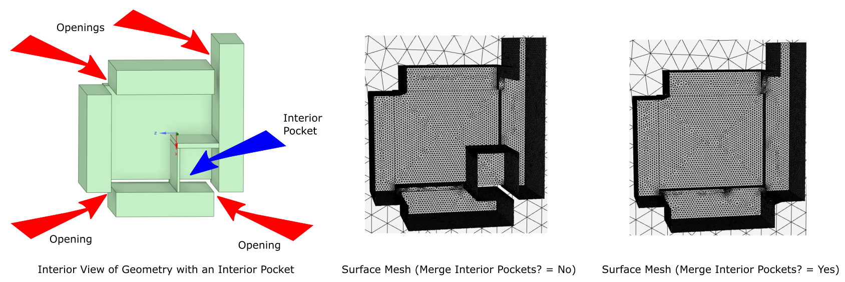
If the Boundary Name Contains... ...Assign Boundary Type to... *mass*inlet* mass flow inlet *press*inlet* pressure inlet *inlet* velocity inlet *mass*outlet* mass flow outlet *outlet* pressure outlet *symmetry* symmetry *far*field* pressure far field *outflow* outflow *wall* wall *overset* overset *internal* or *interior* internal *interface* interface Use the Merge Interior Pockets? field to determine whether or not to extend or expand the surface mesh into any interior cavities or pockets.
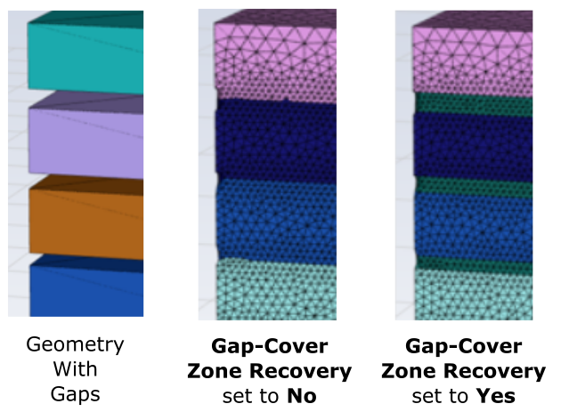
When gap covers are present, use the Gap-Cover Zone Recovery field to determine whether or not to keep or remove the zones representing the cap covers. When set to Yes, the zones representing the gap covers are retained, whereas when set to No (the default), the zones for the gap covers are removed.
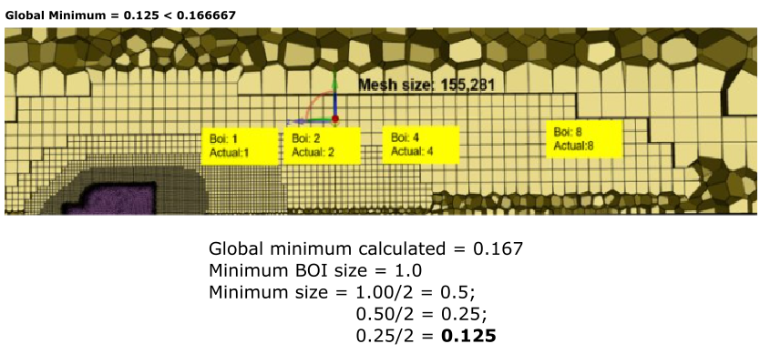
Specify a value for the Global Minimum for the surface mesh. The default value for the Global Minimum is determined by considering your available size controls and bodies of influence.
The workflow first determines the lowest value of all minimum values out of all the size controls, considering both wrap and target size control types (for example, 0.167). Then, the workflow searches for the smallest value for the body of influence (for example, 1). The workflow will then divide the smallest BOI value in half repeatedly (for example, 1/2 = 0.5, 0.5/2 = 0.25, 0.25/2 = 0.125, etc.), until the result is smaller than the smallest minimum value (for example, 0.167). Therefore, in this example, the global minimum is then set to a default value of 0.125.
This leads to an improvement when considering polyhedra and hexahedra cells, where previously, the adjusted minimum size was not utilized and resulted in an increased number of cells.
Once your selections are made, click Generate the Surface Mesh and proceed onto the next task.
The generated surface mesh is applied to all fluid and solid regions (if applicable). By default, the final surface mesh is viewed as separated zones.
If you need to make adjustments to any of your settings in this task, click Revert and Edit, make your changes and click Update, or click Cancel to cancel your changes.