For internal flow simulations with solid model geometries, you can use the Enclose Fluid Regions (Capping) task to cover, or cap, any openings in your geometry in order to later calculate your fluid region(s).
Specify a Name for the capping surface.
Choose the Zone Type for the new cap. Choices include:
velocity-inlet
pressure-outlet
pressure-inlet
pressure-far-field
mass-flow-inlet
outflow
symmetry
wall
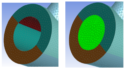
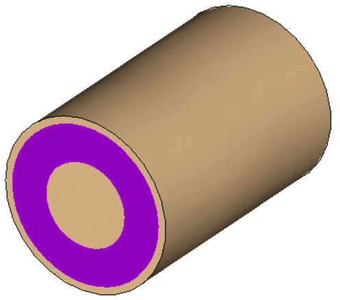
Choose whether the Cap Type will be based on a single surface opening, or if it is an annular opening with two surfaces.
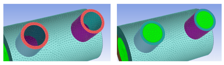
Note: A single surface opening can potentially have more than one face comprising the single surface:
A single surface opening can also mean selecting multiple, distinctly separate, surfaces to create a single cap:
Note: A single named selection using both the inner and outer face is the only valid selection for annular capping using labels.
Choose whether to Select By the label or zone name in the list below.
Note: Labels originate from the CAD geometry, such as from group names in SpaceClaim geometries, or from named selections in DesignModeler geometries.
Select items in the list, or use the Filter Text option in the drop-down to provide text and/or regular expressions in filtering the list (for example, using *, ?, and []). You can also choose the Use Wildcard option in the drop-down to provide wildcard expressions in filtering the list. When you use either
?or*in your expression, the matching list item(s) are automatically selected in the list. Use^,|, and&in your expression to indicate boolean operations for NOT, OR, and AND, respectively. See Filtering Lists and Using Wildcards for more information.Click Advanced Options to access additional controls prior to performing this task. Options include:
Use the Check Cap Self-Intersection? option to control whether or not the system will detect if the capping surface intersects with any other face in the model. If an intersected face is found, it is automatically deleted. To increase the efficiency of the capping task, this option should be set to no.
Use the Max Cap Edge Count Limit option to control the number of edges that can be present on the capping surface.
Click Add Cap(s). The new capping object will appear in the workflow and in the graphics window.
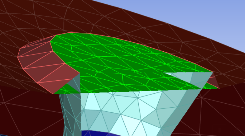
In cases where a face has multiple holes, and only a portion of them will be used for fluid extraction, Fluent will cap all holes on the face, and will only use the capped openings that are required for extracting the fluid region.
If you need to make adjustments to any of your settings in this task, click Revert and Edit, make your changes and click Update, or click Cancel to cancel your changes.
Repeat as needed for additional inlets, outlets, etc., until all openings have been assigned a type and have been created.
Once all openings have been covered, proceed to the next step in the workflow.