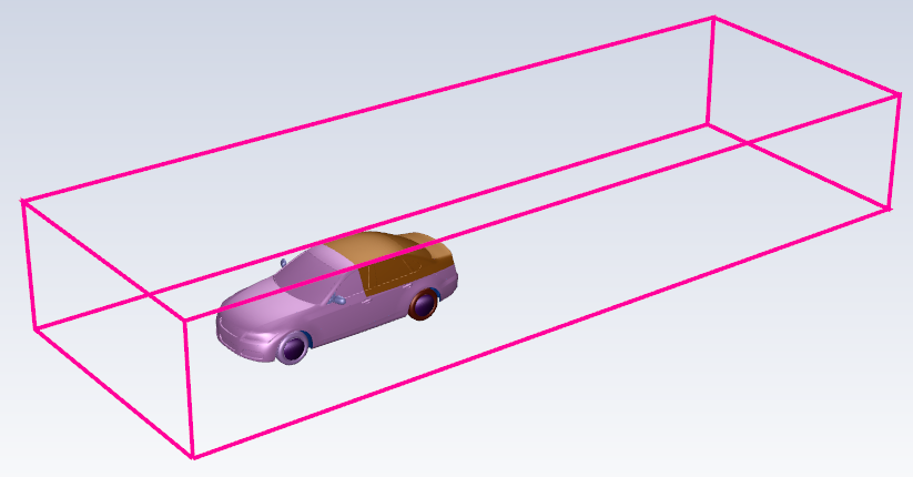
When simulating external flow around an object, your geometry may not contain a fully defined external flow boundary. You can manually create an external flow boundary in this task, by defining a bounding box that surrounds the relevant aspects of your geometry, such as around a vehicle.
Specify a Name for the external boundary, or use the default name (
tunnel).For Method, select Create new boundary if you are creating a new external flow boundary, or select Use existing boundary if the external flow boundary is already defined as part of your imported geometry.
For the Coordinate Specification Method prompt (when you select Create new boundary as the Method), you can choose from the following options:
Use the Ratio relative to geometry size option so that you can define the external flow boundary based on the relative size of selected object(s) or zone(s).
Use the Directly specify coordinates option so that you can explicitly define the location and dimension of the external flow boundary without having to select object(s) or zone(s).
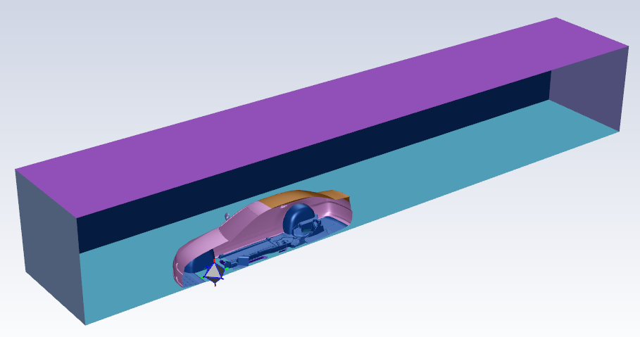
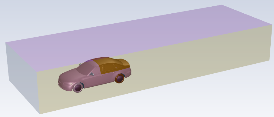
For the Extraction Method, make a selection based on whether you would like to extract the external flow region either as a surface mesh object (a direct surface remesh of the object) or a wrap object. The object setting is applied later when generating the surface mesh.
For new external flow regions, additional settings are required.
When you select Ratio relative to geometry size, choose whether to Select By the object, label, or zone name in the list below.
Select items in the list, or use the Filter Text option in the drop-down to provide text and/or regular expressions in filtering the list (for example, using *, ?, and []). You can also choose the Use Wildcard option in the drop-down to provide wildcard expressions in filtering the list. When you use either
?or*in your expression, the matching list item(s) are automatically selected in the list. Use^,|, and&in your expression to indicate boolean operations for NOT, OR, and AND, respectively. See Filtering Lists and Using Wildcards for more information.Once one or more object(s) or zone(s) is selected, you can define the extents of the external boundaries around the selection by defining a bounding box.
The Box Parameters hold the minimum and maximum extension ratios for the X, Y, and Z dimensions. By default, they are set to extend the dimensions of a bounding box around your selected object(s) or zone(s) out by a factor equivalent to the total singular length of the geometry in the X, Y, and Z directions. You can change the values according to your needs, and the display in the graphics window will change accordingly.
When you select Directly specify coordinates, the Box Parameters hold the minimum and maximum extension distance for the X, Y, and Z dimensions. By default, they are set to values that correspond to the extension ratios, but you can set them to more suitable values as required, and the display in the graphics window will change accordingly.
Once your selections are made, click Create External Flow Boundaries and proceed onto the next task.
If you need to make adjustments to any of your settings in this task, click Revert and Edit, make your changes and click Update, or click Cancel to cancel your changes.