


By default, VBM writes the Rotor_xx_Loads.csv files for each
rotor xx to report the VBM global outputs. These outputs include
the force, moment and power on the rotor disk, as defined in Table 18.3: VBM Global Outputs for Each Rotor, considering the local coordinates
 shown in Figure 18.1: Rotor Disks Schematic. In this
table,
shown in Figure 18.1: Rotor Disks Schematic. In this
table,  ,
,  and
and  repesents the local coordinates and
  stands for the radius of a facet cell. The components of the
time-averaged force on the facet cell are denoted as
stands for the radius of a facet cell. The components of the
time-averaged force on the facet cell are denoted as  ,
,  ,
,  and
and  represents the tangential force on the facet cell. Within this table,
 is the rotor speed,
  is the rotor disk area,
  is the rotor radius and
  is the rotational speed of the rotor. Throughout the simulation, you
have the option of monitoring, printing, writing and/or plotting these global solutions
for any rotor using VBM report definitions. To set up VBM reports using the
VBM Report Definition dialog box, go to:
is the rotational speed of the rotor. Throughout the simulation, you
have the option of monitoring, printing, writing and/or plotting these global solutions
for any rotor using VBM report definitions. To set up VBM reports using the
VBM Report Definition dialog box, go to:
![]() Solution
→ Reports → Definitions
Solution
→ Reports → Definitions
![]() New... → VBM
Report → Rotor...
New... → VBM
Report → Rotor...
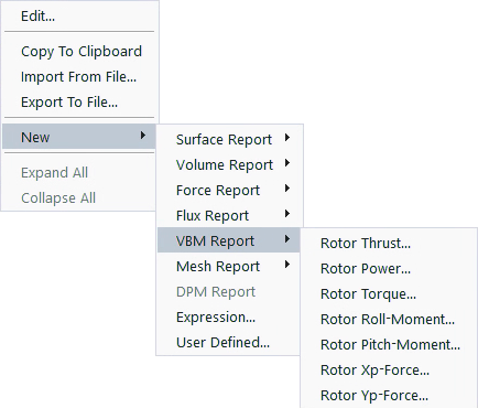
From there, you can choose one of the available report type options. Additionally, you can set the Output Type to if required.
It's important to define VBM reports individually if you intend to have multiple report definitions printed to the Console, written to a file or plotted in the Graphics window. This is useful for monitoring convergence and recording time histories.
Table 18.3: VBM Global Outputs for Each Rotor
| Output Type | Definition - Quantity | Definition - Coefficient |
|---|---|---|
| Xp-force (N) |  |  |
| Yp-force (N) |  |  |
Thrust(N) |  |  |
Roll-moment(N·m) |  |  |
Pitch-moment(N·m) |  |  |
Torque(N·m) |  |  |
Power(W) |  |  |
Note: When reading a Fluent data file, the new collective and cyclic pitches (calculated during rotor trimming) will be printed to the Console. However, they will not be updated within the VBM setup. If you want to continue the simulation using new collective and cyclic pitches, you should update your VBM setup manually.