The continuous fiber model enables you to apply custom correlations for drag, heat transfer, mass transfer coefficients, as well as material properties to the fibers by means of user-defined functions (UDFs). You are provided with a C template file named fiber_fluent_interface.c that contains source code for the drag, heat transfer, mass transfer coefficient, and the fiber property UDFs. You will need to modify this UDF source file to suit your application, compile it, and hook the resulting UDF object(s) to the fiber model. This process is described below.
For more information, see the following sections:
Before you can edit the UDF template and create your custom UDF for drag, heat
transfer or mass transfer coefficient, you must copy the fiber
directory to your working directory. The fiber directory contains
all of the libraries and support files that are required to compile UDFs for the fiber
model and build shared libraries for the architecture that you specify.
Make a local copy of the fiber directory by copying it from the path below to your working directory.
path/ansys_inc/v242/fluent/fluent24.2.0/addons/fiber/
where
path
is the directory in which you have installed Ansys Fluent.
Open a Visual Studio
.NETDOS prompt.Make a local copy of the fiber folder (not a symbolic link) by copying it from the folder below to your working folder.
path\ANSYS Inc\v242\fluent\fluent24.2.0\addons\fiber\where
pathis the folder in which you have installed Ansys Fluent (by default, the path is C:\Program Files).
Now that you have copied the fiber directory to your working directory, you can edit the UDF template file and customize it to fit your model needs.
In your working directory, change directories to fiber/src. The /src directory contains the UDF template source file fiber_fluent_interface.c.
In the /src directory, use any text editor and edit fiber_fluent_interface.c.
Scroll down to the bottom of the fiber_fluent_interface.c file to the section that contains concatenated functions for friction factor (drag coefficient), heat transfer coefficient, mass transfer coefficient, fiber viscosity, fiber density, fiber thermal conductivity, fiber specific heat, and vapor liquid equilibrium, respectively. These are the UDFs that you can modify and customize.
Edit the function(s) you require for your particular application. Save fiber_fluent_interface.c and overwrite the existing file.
Important: Do not save the file with another name because it will not be recognized by the system.
Important: The function names of the templates
user_friction_factor,user_heat_transfer_coefficient, anduser_mass_transfer_coefficientmust not be altered because they are called by other routines in the continuous fiber model.
Below is an example of a heat transfer coefficient UDF that is defined in
fiber_fluent_interface.c. The function is taken from Kase and
Matsuo 291 and is implemented as the
kase-matsuo-1 option in the fiber model. The function name
user_heat_transfer_coefficient
must not, under any circumstances, be altered because it is called by
other functions in the continuous fiber model.
There are two arguments to the
user_heat_transfer_coefficient UDF:
Fiber and Local_Fiber_Data_Type.
Fiber *f is a pointer to the fiber structure that contains
information about the fiber and Local_Fiber_Data_Type *fd
accesses temporary variables that are needed during the calculation of the fiber.
In the sample UDF below, a loop is performed over all fiber grid cells using the
macro FIB_N(f) which represents the number of grid cells for the
fiber f. The Reynolds number is computed based on the relative
velocity,  (
(ABS(FIB_C_U(f,i)-fd->up[i])); the fiber
diameter, FIB_C_D(f,i); the density of the surrounding fluid,
fd->rho[i] and the viscosity of the surrounding fluid,
fd->vis[i]. The heat transfer coefficient  is computed from the Nusselt number using the thermal conductivity of
the surrounding fluid,
is computed from the Nusselt number using the thermal conductivity of
the surrounding fluid,  , (
, (fd->k[i]) and is stored in
fd->alpha[i].
 void
 user_heat_transfer_coefficient(Fiber *f, Local_Fiber_Data_Type *fd)
 {
  int i;
  real Red, Nud;

  /* model from Kase/Matsuo (1967) */
  for (i=0; iFIB_N(f); i++)
  {
    /* compute Reynolds number based on relative velocity */
    Red = ABS(FIB_C_U(f,i)-fd->up[i])*FIB_C_D(f,i)*fd->rho[i]/fd->vis[i];
    Nud = 0.42*pow(Red, 0.334);
    /* store heat transfer coefficient for latter use */
    fd->alpha[i] = Nud*fd->k[i]/FIB_C_D(f,i);
   }
 }
All variables and macros that are used in
user_heat_transfer_coefficient are defined in header files
provided with the continuous fiber model. For example, you will find the type definition
Fiber and the macros that are used to access variables of a
single fiber in the header file fiber.h. Temporary variables used
in the type definition of Local_Fiber_Data_Type can be found in
the header file fib-mem.h.
Important: Note that you must not modify the header files provided with the continuous fiber model. Otherwise the compiled library will not be compatible with Ansys Fluent and will show run time errors.
You can also calculate fiber material properties using UDFs. Ansys Fluent provides a UDF template for every fiber property. You can modify the UDF templates for your specific case.
The template for the fiber density is as follows:
real User_Fiber_Specific_Heat(Fiber *f, real temp, real liq, int i)
{
  real yi[MAX_SPE_EQNS];
  real cp_p;
/* compute cp based on FLUENT's standard procedure selected in materials panel */
  cp_p = Specific_Heat(FIB_MATERIAL_POLYMER(f), temp, 0., yi);
  if (FIB_DRY_SPINNING(f))
  {
    real cp_s;
    cp_s = Specific_Heat(FIB_MATERIAL_SOLVENT(f), temp, 0., yi);
    return cp_p*(1.-liq)+cp_s*liq;
   }
  return cp_p;
}
Important: The function names of the templates User_Friction_Factor,
User_Heat_Transfer_Coefficient,
User_Mass_Transfer_Coefficient,
User_Fiber_Viscosity,
User_Fiber_Density,
User_Fiber_Thermal_Conductivity,
User_Fiber_Specific_Heat, and
User_Fiber_Vle must not be altered since they are called by
other routines of the continuous fiber model.
All variables and macros defined in the header files are provided with the
continuous fiber model. For example, you will find the type definition
Fiber and the macros to access variables of a single fiber in
the header file fiber.h. The temporary variables used in the type
definition of Local_Fiber_Data_Type can be found in the header
file fib-mem.h.
Important: You must not modify the header files provided with the continuous fiber model. Otherwise the compiled library will not be compatible with Ansys Fluent resulting in runtime errors (messages will be printed in the console).
Once you have customized the UDF template fiber_fluent_interface.c for your fiber model application, you are now ready to compile the source file using the text interface. Follow the procedure below for Linux Systems and Windows Systems, respectively.
In the /fiber in your working directory, run the
make command that will compile your fiber mode UDF and build
a shared library for the architecture you are running. To do this, type the following
command at the prompt:
make -f Makefile-client FLUENT_ARCH=your_arch
where your_arch is replaced by the architecture of the
machine you are running (for example, lnx86).
For example, if your computer architecture is lnx86 type
the following command in a terminal session:
make -f Makefile-client FLUENT_ARCH=lnx86
To identify the architecture of the machine you are running on, scroll up the Ansys Fluent console window to the message that begins with “Starting”.
When you run the make process, the source code
(fluent_fiber_interface.c) will be compiled into object code and
a shared library will be built for the computer architecture and version of Ansys Fluent you
are running. Messages about the compile/build process will be displayed on the console
window. You can view the compilation history in the log file that is saved in your
working directory. Below is an example of console messages for a lnx86 architecture
running a 2D version of Ansys Fluent.
 Working...
 for d in lnx86[23]*; do \
    ( \
       cd $d; \
       for f in ../../src*.[ch] ../../src/makefile; do \
          if [ ! -f ’basename $f’ ]; then \
            echo "# linking to " $f "in" $d; \
            ln -s $f .; \
         fi; \
       done; \
       echo ""; \
       echo "# building library in" $d; \
       make -kmakelog 2&1; \
       cat makelog; \
   ) \
 done
 # linking to ...  myudf.c in lnx86/2d

 # building library in lnx86/2d
 make[1]: Entering directory ..../udf_names.c
 # Generating udf_names
 make[2]: Entering directory ..../fluent_fiber_interface.c
 make libudf.so ...
 # Compiling udf_names.o ...
 # Compiling profile.o ...
 # Linking libudf.so ...
 make[2]: Leaving directory ..../udf_names.c
 make[1]: Leaving directory ..../fluent_fiber_interface.c

 You can also see the ’log’-file in
 the working directory for compilation history

 Done.
Make a local copy of the
fiberfolder. Do not create a shortcut.Create a directory for the custom
fiberlibraries (for example, /home/custom-build).Copy the
fiberlibrary from the installation of Ansys Fluent (Ansys Inc\v242\fluent\fluent24.2.0\addons) to your newly created directory.
Open the Visual Studio .NET DOS prompt (see Compiler Requirements for Windows Systems in the Ansys, Inc. Installation Guides for compilers that are compatible with Ansys Fluent).
Set the
FLUENT_INCenvironment variable to the current Ansys Fluent installation directory, for example:FLUENT_INC="<driveletter>\ANSYS Inc\v242\fluent"where
<driveletter>is the target drive letter including the colon (for example,D:).Enter the fiber\src folder:
cd fiber/srcMake changes to the fiber_fluent_interface.c file.
Return to the fiber folder:
cd ..Issue the following command in the command window:
build_fiber_udf.bat
Define the
FLUENT_ADDONSenvironment variable to correspond to your customized version of the continuous fiber module in one of following ways:Set the path to
FLUENT_ADDONSglobally.In the Environment tab of Fluent Launcher, enter information for
FLUENT_ADDONSin the Other Environment Variables field, for example:FLUENT_ADDONS=<driveletter>\home\custom-buildwhere
<driveletter>is the target drive letter including the colon (for example,D:). Note that there should be no spaces in the above path.
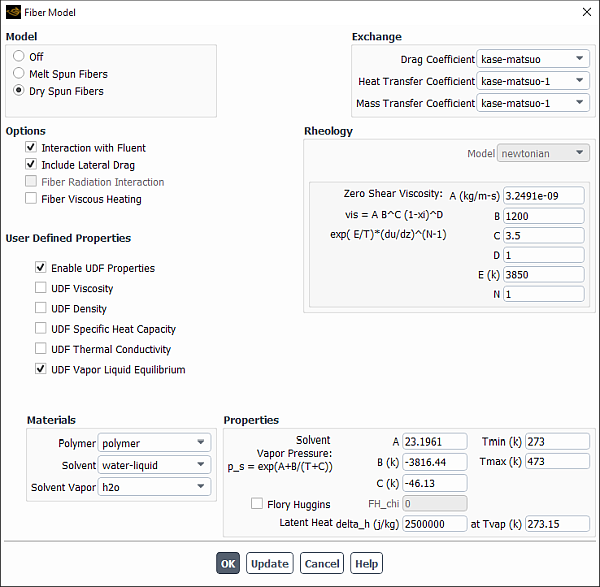
Once you have successfully compiled your continuous fiber model UDF(s), the
user-defined option will appear in drop-down lists for
parameters under Exchange in the Fiber Model
dialog box (Figure 34.12: The Fiber Model Dialog Box). To hook your UDF to a
particular fiber model parameter, simply select user-defined from
the drop-down list for Drag Coefficient, Heat Transfer
Coefficient, or Mass Transfer Coefficient and click
.
If you want to use UDFs to define fiber material properties, select the Enable UDF Properties check box, and then enable individual property UDFs under the User Defined Properties group box.