


Fluent VBM replaces the rotor system with momentum sources acting on a layer of cells for each rotor zone. These cells can be marked in the mesh as a separate cell zone, called Embedded Disk, or can be searched in the mesh when cut by a disk surface geometry, called Floating Disk. In this section, the meshing guideline for each mode and general considerations to create a proper mesh for VBM simulations is described.
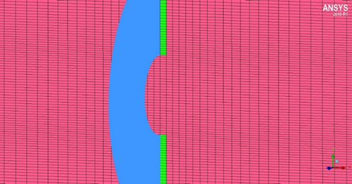
For Embedded Disk, an internal surface in the shape of a flat disk should be created in the flow domain at the location of the rotor. In the CAD, this surface should be marked as an internal wall or internal surface that will be discretized by a single layer of nodes, such that the mesh is continuous across the surface (for example, no duplicate nodes). The dead part of the rotor near the hub - the cutout - can be neglected. Figure 18.5: Schematic of a Cut Through a Structured VBM Grid. The Green Cells Are Assigned to the VBM shows the disk analogue of a simple rotor and its cutout.
A single uniform layer of prisms or hexahedral cells should be extruded from the cell faces attached to the disk in the direction normal to the disk. Although there is no definitive rule regarding the thickness of these cells, it is recommended that the layer remains between 1/40th to 1/100th of the diameter of the disk. The single prismatic cell layer in the direction downstream of the disk should be marked as a separate zone (rotor zone).
Note: Pyramids and tetra cells attached to the disk cells to provide the blending with the rest of the grid are part of the flow domain, not the rotor zone.
For the Floating Disk mode, there is no need to create any rotor disk and corresponding prismatic layers in the mesh. Instead, the floating disk can be created through the VBM's graphical user interface based on the rotor geometry definition and orientation (Rotor Radius [m], Rotor Root Cutout [m], Rotor Disk Origin, and Rotor Disk Normal Vector), see Meshing Guidelines and Creating the VBM Disk for more details. In case the disk orientation is set based on Rotor Disk Angles, Fluent will calculate the disk normal vector components automatically. After pressing for each Active Rotor Zone, the following steps will take place to create and select the floating disk:
Creates a Custom Field Function named radius-fdisk-RotorName to calculate the radius from the Rotor Disk Origin. (RotorName refers to the Active Rotor Name)
Creates a Plane Surface named plane-fdisk-RotorName based on the Rotor Disk Origin and Rotor Disk Normal Vector.
Creates the floating disk, named srf-fdisk-RotorName by cutting the plane-fdisk-RotorName using an iso-clip to include the area with radius-fdisk-RotorName between Rotor Root Cutout [m] and Rotor Radius [m].
Selects srf-fdisk-RotorName in the graphical user interface under Rotor Surface.
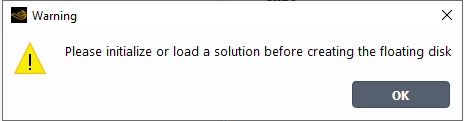
Note: The iso-clip will only be activated if a solution is present. Therefore, an initial solution should be loaded or initialized before pressing . Otherwise, Fluent will give a warning message.
The floating disk can be any surface with any shape and not necessarily planar like the disk created automatically through the graphical user interface. There are several ways to create a surface in Fluent. For non-planar surface (for example, a conical surface), you can imprint the disk from a .stl file.
The VBM supports both structured and unstructured hybrid grids. Mesh clustering is recommended near the disk and on the inner and outer circumference of the disk since these are regions where interference effects and loss models are usually acting. The current default quadratic tip loss model, for example, will not produce smooth solutions if the grid in the range 0.96 ≤ r/R ≤ 1.0 is very coarse.
Attention must be paid to the size of the inlet/exit boundaries of the computational domain, particularly for heavy helicopters in hover, to ensure that the mass flow rate of air passing through the domain is many times larger than the mass flow through all the rotors. If this detail is overlooked the overall simulation might diverge, converge very poorly, or the rotors may not be able to produce the desired amount of thrust. The reason is that VBM simulations (and also higher-fidelity methods, such as the MRF) are over-specified: while rotorcraft or propeller-driven aircraft will fly at a speed resulting from the balance of forces acting on them, in the CFD simulation this speed is specified by you. It is then possible to specify speeds that are incompatible with the settings of the rotor. For this reason, for example, a suitable non-zero mass flow rate should be specified on the farfield boundaries of a helicopter in hover.
Figure 18.5: Schematic of a Cut Through a Structured VBM Grid. The Green Cells Are Assigned to the VBM
Finally, the grid in the downstream of the rotor should have sufficient clustering to capture the complex effects of the momentum change imparted by the VBM and the interaction of the wake of the rotor with other rotors (for example, main and tail rotors of a helicopter) or with other components of the aircraft/rotorcraft. Since the load distribution of a rotor is generally non-uniform, secondary vortices are likely to appear and should be captured in as much detail as possible.