Some terminology must be introduced to distinguish between different types of cells and faces in a partitioned mesh. Note that this nomenclature applies only to parallel coding in Ansys Fluent.
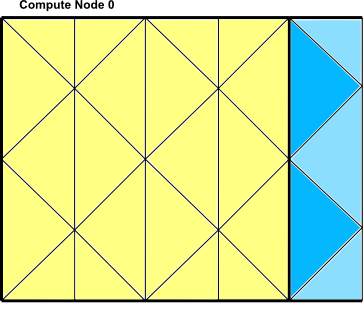
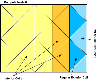
There are broadly two types of cells in a partitioned mesh: interior cells and exterior cells (Figure 7.6: Partitioned Mesh: Cells). Interior cells are fully contained within a mesh partition. Exterior cells to a partition are not contained within that mesh partition but are connected to a node on its interface with one or more neighboring partitions. If an exterior cell shares a face with an interior cell then it is referred to as a regular exterior cell. If an exterior cell shares only an edge or a node with an interior cell then it is referred to as an extended exterior cell. Exterior cells on one compute node correspond to the same interior cells in the adjacent compute node. (Figure 7.2: Partitioned Mesh Distributed Between Two Compute Nodes). This duplication of cells at a partition boundary becomes important when you want to loop over cells in a parallel mesh. There are separate macros for looping over interior cells, exterior cells, and all cells. See Looping Macros for details.
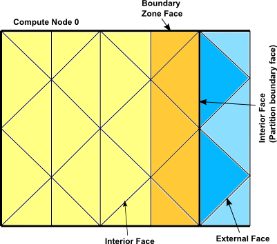
There are three classifications of faces in a partitioned mesh: interior, boundary zone, and external (Figure 7.7: Partitioned Mesh: Faces). Interior faces have two neighboring cells. Interior faces that lie on a partition boundary are referred to as "partition boundary faces." Boundary zone faces lie on a physical mesh boundary and have only one adjacent cell neighbor. External faces are non-partition boundary faces that belong to exterior cells. External faces are generally not used in parallel UDFs and, therefore, will not be discussed here.
Note that each partition boundary face is duplicated on adjacent compute nodes (Figure 7.2: Partitioned Mesh Distributed Between Two Compute Nodes). This is necessary so that each compute
node can calculate its own face values. However, this duplication can result in face data
being counted twice when UDFs are involved in operations that involve summing data in a
thread that contains partition boundary faces. For example, if your UDF sums data over all
of the faces in a mesh, then as each node loops over its faces, duplicated partition
boundary faces can be counted twice. For this reason, one compute node in every adjacent set
is assigned by Ansys Fluent as the "principal" compute node, with respect to
partition boundary faces. In other words, although each face can appear on one or two
partitions, it can only "officially" belong to one of them. The Boolean macro
PRINCIPAL_FACE_P(f,t) returns TRUE if
the face f is a principal face on the current compute node.
You can use PRINCIPAL_FACE_P to test whether a given face is the
principal face, before including it in a face loop summation. In the sample source code
below, the area of a face is added to the total area only if it is the principal
face.
Important: PRINCIPAL_FACE_P can be used only in compiled UDFs.
Example
begin_f_loop(f,t)
 if PRINCIPAL_FACE_P(f,t) /* tests if the face is the principal face
               FOR COMPILED UDFs ONLY */
 {
   F_AREA(area,f,t);  /* computes area of each face */
   total_area +=NV_MAG(area); /* computes total face area by
                 accumulating magnitude of each
                 face’s area */
 }
 end_f_loop(f,t)
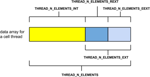
Each thread stores the data associated with its cells or faces
in a set of arrays. For example, pressure is stored in an array and
the pressure for cell c is obtained by accessing
element c of that array. Storage for exterior
cell and face data occurs at the end of every thread data array. For
a cell thread, data for regular exterior cells occurs before that
for extended exterior cells, as shown in Figure 7.8: Exterior Thread Data Storage at End of a Thread Array.
Ansys Fluent creates a complete extended exterior cell neighborhood based on interface faces and corner nodes. This makes certain operations easier (such as mesh manipulations and solver gradient reconstructions) and enhances the performance of such operations. The solver uses only the regular neighborhood and hence solver-related data is filled only for the regular exterior cells and not for the extended exterior cells.
Figure 7.9: Regular Neighborhood Includes the Dark Blue Triangles (Connected to the Partition Interface Faces)
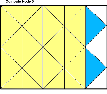
Figure 7.10: Extended Neighborhood Includes Both the Dark Blue and the Light Blue Triangles (Connected to the Partition Interface Nodes)