


Many applications utilize battery systems in which multiple batteries are connected in
series or in parallel. In Ansys Fluent, the MSMD approach has been extended to simulate battery
systems. When simulating a battery pack, Ansys Fluent uses the continuous zone method in which two
potential equations are solved over all the conductive zones continuously. In a single battery
case, two potential equations can be interpreted as  and
and  , where
  is the potential field of the positive electrode and
  is the potential of the negative electrode. In a multiple cell system, the
situation is more complicated as explained below.
is the potential of the negative electrode. In a multiple cell system, the
situation is more complicated as explained below.
Figure 19.3: Solution Domain for Two Potential Equations in a Battery Pack System schematically shows an example in which three battery cells are connected in series.
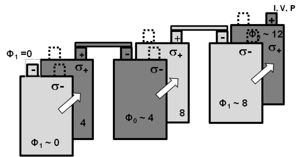
The positive tab of one battery is connected to the next battery’s negative tab. As a
result, the  of the first battery is about at the same level as the
  of the second battery. In other words,
  of the first battery and
  of the second battery should be solved in the same domain. We still can use
only two potential fields to capture the electric field, however, we can no longer interpret them
as the potential fields of the positive and negative electrodes.
of the second battery should be solved in the same domain. We still can use
only two potential fields to capture the electric field, however, we can no longer interpret them
as the potential fields of the positive and negative electrodes.
In Figure 19.3: Solution Domain for Two Potential Equations in a Battery Pack System, different shades of gray are used for cell zones to demonstrate the different equations being solved (for the convenience of bookkeeping, we introduce the "level" of a zone to mark which equation needs to be solved for a given zone):
An active zone (where electro-chemical reactions occur) belongs to two "levels". Both
 and
and  are solved:
  is solved for the zones at the odd level and
  is solved in the zones at the even level.
A passive zone (tab or busbar) belongs to only one level, where only one potential equation is solved.
For example, for N batteries connected in series, there will be N+1 levels. Except for the first and the last levels, each level is isolated in the sense that there is no flux across its boundary. Two levels are coupled only through the equations source terms. Two potential equations are solved continuously across all the conductive zones. In a passive zone, however, only one potential equation is solved, and the second equation is excluded by setting the electrical conductivity to zero.
Battery Connections
Batteries in a pack can be connected through either “real connections” or “virtual connections”.
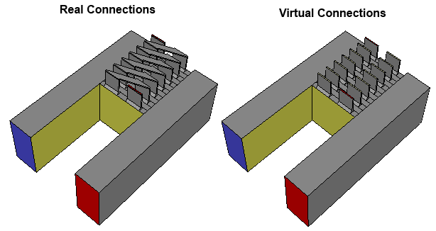
Real connections are busbars that are physically resolved and meshed in the model.
Virtual connections are busbars or battery tab volumes that are not explicitly resolved in the model. Instead, the connection information is provided in a battery connection definition file as described in Specifying Electric Contacts. The solver reads this information and sets the electric boundary conditions for each individual battery through the virtual connections.
Using virtual connections saves the time and effort of meshing busbar and tab volumes, which are usually very thin and difficult to mesh. The disadvantage is that electric resistance and Joule heating are not considered in these unresolved volumes.
You can select the method that best suits your needs in your simulation. Refer to Specifying Electric Contacts for the details on using the battery virtual connections in a battery pack.