Ansys Fluent solves the equations of fluid flow and heat transfer by default in a stationary (or inertial) reference frame. However, there are many problems where it is advantageous to solve the equations in a moving (or non-inertial) reference frame. These problems typically involve moving parts, such as rotating blades, impellers, and moving walls, and it is the flow around the moving parts that is of interest. In most cases, the moving parts render the problem unsteady when viewed from a stationary frame. With a moving reference frame, however, the flow around the moving part can (with certain restrictions) be modeled as a steady-state problem with respect to the moving frame.
Ansys Fluent’s moving reference frame modeling capability allows you to model problems involving moving parts by allowing you to activate moving reference frames in selected cell zones. When a moving reference frame is activated, the equations of motion are modified to incorporate the additional acceleration terms that occur due to the transformation from the stationary to the moving reference frame.
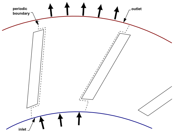
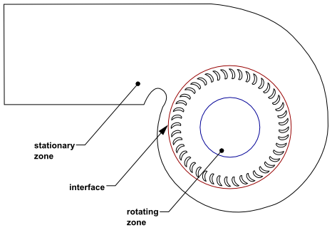
For many problems, it may be possible to refer the entire computational domain to a single moving reference frame (see Figure 2.1: Single Component (Blower Wheel Blade Passage)). This is known as the single reference frame (or SRF) approach. The use of the SRF approach is possible; provided the geometry meets certain requirements (as discussed in Flow in a Moving Reference Frame). For more complex geometries, it may not be possible to use a single reference frame (see Figure 2.2: Multiple Component (Blower Wheel and Casing)). In such cases, you must break up the problem into multiple cell zones, with well-defined interfaces between the zones. The manner in which the interfaces are treated leads to two approximate, steady-state modeling methods for this class of problem: the multiple reference frame (or MRF) approach, and the mixing plane approach. These approaches will be discussed in The Multiple Reference Frame Model and The Mixing Plane Model. If unsteady interaction between the stationary and moving parts is important, you can employ the sliding mesh approach to capture the transient behavior of the flow. The sliding meshing model will be discussed in Flows Using Sliding and Dynamic Meshes.