


This preface is divided into the following sections:
The Ansys Fluent Tutorial Guide contains a number of tutorials that teach you how to use Ansys Fluent to solve different types of problems. In each tutorial, features related to problem setup and postprocessing are demonstrated.
Depending on your familiarity with computational fluid dynamics and the Ansys Fluent software, you can use this tutorial guide in a variety of ways.
If you are a beginning user of Ansys Fluent you should first read and solve Tutorial 1, in order to familiarize yourself with the interface and with basic setup and solution procedures. You may then want to try a tutorial that demonstrates features that you are going to use in your application.
You may want to refer to other tutorials for instructions on using specific features, such as custom field functions, mesh scaling, and so on, even if the problem solved in the tutorial is not of particular interest to you.
If you are an experienced Ansys Fluent user, you can read and/or solve the tutorial(s) that demonstrate features that you are going to use in your application.
You may want to refer to other tutorials for instructions on using specific features, such as custom field functions, mesh scaling, and so on, even if the problem solved in the tutorial is not of particular interest to you.
Several typographical conventions are used in this manual’s text to help you find commands in the user interface.
Different type styles are used to indicate graphical user interface items and text interface items. For example:
Iso-Surface dialog box surface/iso-surfacetext commandThe text interface type style is also used when illustrating exactly what appears on the screen to distinguish it from the narrative text. In this context, user inputs are typically shown in boldface. For example,
solve/initialize/set-fmg-initializationCustomize your FMG initialization: set the number of multigrid levels [5] set FMG parameters on levels .. residual reduction on level 1 is: [0.001] number of cycles on level 1 is: [10]100residual reduction on level 2 is: [0.001] number of cycles on level 2 is: [50]100Mini flow charts are used to guide you through the ribbon or the tree, leading you to a specific option, dialog box, or task page. The following tables list the meaning of each symbol in the mini flow charts.
Table 1: Mini Flow Chart Symbol Descriptions
Symbol Indicated Action 
Look at the ribbon 
Look at the tree 
Double-click to open task page 
Select from task page 
Right-click the preceding item For example,
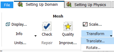
Setting Up Domain → Mesh
→ Transform → Translate...indicates selecting the Setting Up Domain ribbon tab, clicking Transform (in the Mesh group box) and selecting Translate..., as indicated in the figure below:
And
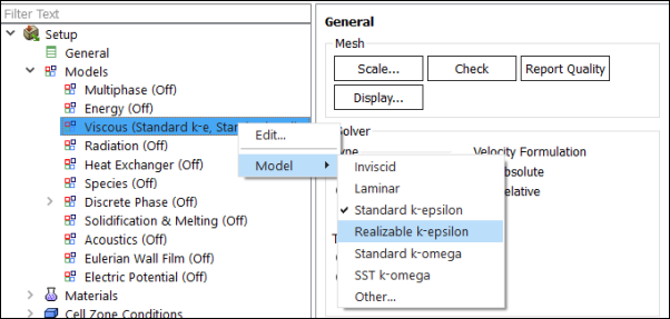
Setup → Models → Viscous Model → Realizable k-epsilonindicates expanding the Setup and Models branches, right-clicking Viscous, and selecting Realizable k-epsilon from the Model sub-menu, as shown in the following figure:
And
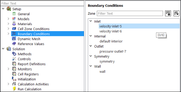
Setup → Boundary
Conditions → velocity-inlet-5indicates opening the task page as shown below:
In this manual, mini flow charts usually accompany a description of a dialog box or command, or a screen illustration showing how to use the dialog box or command. They show you how to quickly access a command or dialog box without having to search the surrounding material.
In-text references to File ribbon tab selections can be indicated using a "/". For example File/Write/Case... indicates clicking the File ribbon tab and selecting Case... from the Write submenu (which opens the Select File dialog box).